T10 Installation Notes v1.7
Generic T10 Installation Notes v1.7.doc 12.08.2015
Page 19
5.5.8 CAN Installation – Vehicle (T10-Micro v4, T10-Lite 5wire & 9wire)
The CAN (vehicle) protocols supported are as follows:
1. EOBDII (via J1962) (Cars and Light Commercial Vehicles)(CAN Micro’s & 9 wire 70-35A).
2. K-Line (CAN Micro’s & 9 wire – 70-30A hardware).
3. ISO 9041 (CAN Micro’s & 9 wire – 70-30A hardware).
Cars and Light Commercial Vehicles
All petrol engine vehicles manufactured since 2000 should be EOBD compliant.
Some manufacturers began incorporating On-Board Diagnostic systems as early as 1994,
however not all are 100% compliant. All diesel engine vehicles are expected to have support
from 2004.
There are currently 5 CAN communication protocols of which 3 are currently supported by the
T10 range of CAN compatible products. The 5 communication protocols are as follows:
• ISO 9141.
• Keyword 2000 (K-Line) (originally a European protocol).
• J1850 PWM (pulse width modulated) protocol used by Ford.
• J1850 VPW (variable pulse width modulated) used by General Motors in USA.
• CAN (Controller Area Network) European Standard.
It is the 1
st (
ISO 9141) 2
nd
(K-Line)(T10-Micro v4) and 5
th
format (“CAN 11/29 bit
addressing”) that is currently supported by the T10-Micro and T10-Lite.
If you are in doubt of the format available on your vehicle then it is advisable to seek
professional advice before connecting.
1. You can use a CAN diagnostics meter to interrogate CAN format and there are
various types available in the market place. If you require further information on one
of these devices then please contact Trakm8 sales.
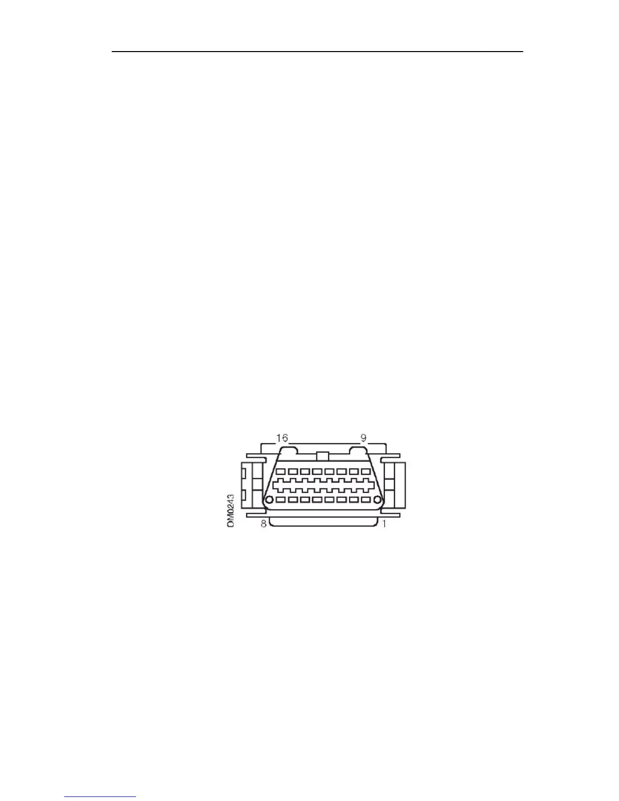
2. It is normally possible to tell which protocol is in use on a specific vehicle by
examining the diagnostic socket of the vehicle. (J1962 connector as shown below)
This is usually found within the driver or passenger compartment of the vehicle as the connector
by design has to be easily located by the service engineer when the vehicle goes in for service.
• If the J1962 diagnostic socket has a pin in the 7
th
& 15
th
position, then the
vehicle uses either the ISO 9141 or Keyword 2000 protocol. Connect the wire
in the 7
th
or 15
th
position to the
• If the J1962 diagnostic socket has a pin in the 2
nd
& 10th position, then the
vehicle uses one of the SAE J1850 protocols.
• If the J1962 diagnostic socket has a pin in the 6
th
& 14
th
position, then the
vehicle is likely to use the CAN protocol. Connect the wire in the 6
th
position
(CANH) to the Green/white stripe wire and the wire in the 14
th
position
(CANL) to the Blue/white stripe wire in the T10 wiring loom.