T10 Installation Notes v1.7
Generic T10 Installation Notes v1.7.doc 12.08.2015
Page 20
NOTE
IF the J1962 connector does NOT have an open center slot in the middle of the
connector then it is NOT 12v Compatible. When the center slot of the
connector contains an obstruction this is indicative of the system being 24v
operation and the obstruction is designed to prevent 12v systems from being
connected to 24v.
NOTE
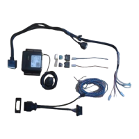
For cars and light commercial vehicles, there is an additional CAN Adaptor T-Piece (CAB782)
available.
The CAN Adaptor T-Piece (CAB782) provide a non-intrusive method of connecting to the J1962
socket (where possible). It has a separate J1962 Socket which replaces the vehicles own socket,
allowing a diagnostic tool to be connected without having to disconnect the T-Piece.
If using the T-Piece, the replacement J1962 socket may not fit back into the original socket
location on the vehicle, for this situation a mounting bracket is also supplied. This can be fixed to
the original location or screwed down securely using suitable mounting hardware to keep it in
place.
It is important to note that the T-piece is not compatible with all vehicle types due to the fact
that some manufactures use J1962 sockets that are molded to a bracket or even part of the ECU
itself. Under these circumstances a direct connection is your only option.
The wiring details are shown below:
EOBD (5wire (70-15A-XXXXA/70-20A-XXXXA) and 9wire (70-35A-XXXXA) models
J1962 connector Pin 6 = CAN High to the Green/White tracer (Pin 8).
J1962 connector Pin 14 = CAN Low to the Blue/White tracer (Pin 9).
K-LINE (9wire PTO model (70-30A-XXXXA) ONLY)
J1962 connector Pin 7 = K-Line to the Green/White tracer (Pin 8).
Testing
Once installed, the equipment should be tested to ensure that it is operating satisfactorily and
that the positions of the installed items do not impair the driver’s ability to control and operate
the vehicle in any way. Follow the vendor specific commissioning procedure to ensure that your
T10 is communicating data to the host server.
The T10 ranges of products ALL have a single RED LED to give visual indication to the fitter/user.
These visual indications are as follows:
The unit has communicated with the server and acquired a 3D
GPS fix and is ready for journey operation. The LED during
periods of awake will indicate GSM/GPRS/GPS and CAN status as
described in engineering screen 1.
The flashing sequences will also be dependent on whether the
vehicle is in a journey and also whether it is a CAN installation.
(See Engineering mode).