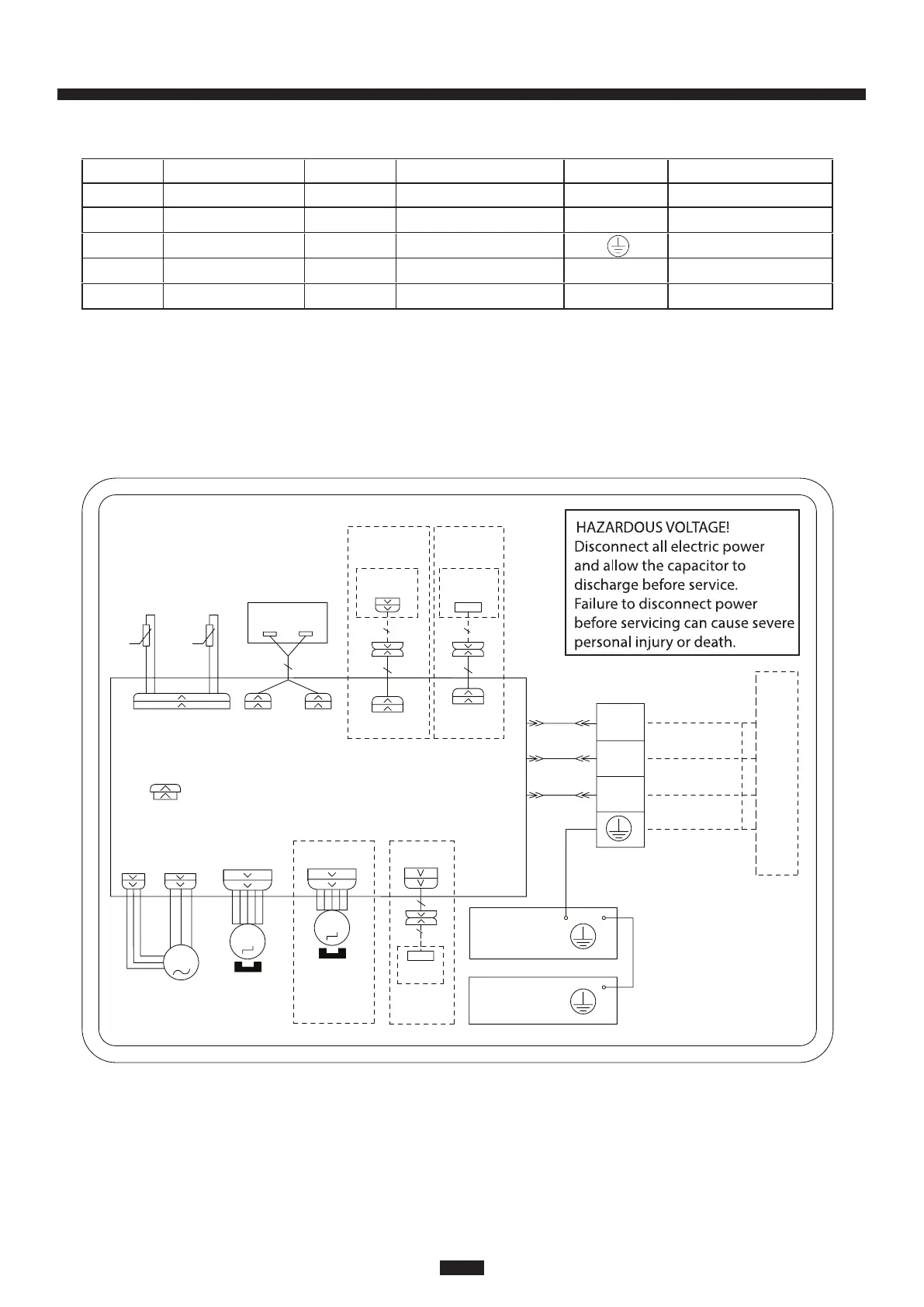
Wiring Diagrams
Note: A "Jumper Cap" may be used to determine fan speed and the swing angle of horizontal louver for this
model. The unit will not operate without the correct jumper cap. If "Jumper Caps" are installed on the original
electrical board, they must be removed and installed on a replacement electrical board.
Symbol Symbol Color Symbol Symbol Color Symbol Name
WH White GN Green CAPJumper cap
YE Yellow BN Brown COMP Compressor
RD Red BU Blue Grounding wire
YE/GN Yellow/Green BK Black
VT Violet OG Orange
STEPPING
CAP
BLOCK
TERMINAL
G
EVAPORATOR
JUMP
AP2: MAIN BOARD
YEGN
BK
BN
YEGN
N1
3
2
N(1)
XT1
BU
AC-L
COM-OUT
MOTOR
OUTDOOR UNIT
T-SENSORDISP2DISP1
RT1
θ
AP1
ROOM
TUBE
TEMP.SENSOR
TEMP.SENSOR
DISPLAY BOARD
RECEIVER AND
θ
RT2
SWING-UD
M2
ELECTRIC BOX
G
WH(BU)
BK
RD(BN)
M1
AP4
WIFI
WIFI
MODULE
SWING-LR
M3
STEPPING
MOTOR
LEFT-RIGHT
COM-MANUAL
AP3
WIRED
CONTROLLER
DRY-C
AP5
DRY
CONTACT
(DOOR-C)
PGF PG
FAN
MOTOR
OPTIONAL
OPTIONAL
OPTIONAL OPTIONAL
GN(YEGN)
NOTE: The wiring diagrams in this guide are included as a reference. The manufacturer
has a policy of continuous product and product data improvement and reserves the
right to change design and specications without notice. Always check the unit
nameplate and wiring diagram for the actual unit requirements.
Indoor Cooling and Heat Pump Unit 9K-12K
31
17 Series Mini-Split