EasyManua.ls Logo

Trane Technologies Voyager 3 User Manual

Trane Technologies Voyager 3
92 pages
To Next Page IconTo Next Page
Page #1 background imageLoading...
Page #1 background image
SAFETY WARNING
Only qualified personnel should install and service the equipment. The installation, starting up, and servicing of heating, ventilating, and air-conditioning equipment
can be hazardous and requires specific knowledge and training. Improperly installed, adjusted or altered equipment by an unqualified person could result in death or
serious injury. When working on the equipment, observe all precautions in the literature and on the tags, stickers, and labels that are attached to the equipment.
November 2022
RT-SVX34V-EN
Installation, Operation, and Maintenance
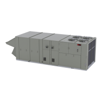
Voyager™ 3
Packaged Rooftop Air Conditioners with Symbio™
700 Controls
27.5 to 50 Tons - 60 Hz
22.9 to 41.7 Tons (82-142 kW) - 50 Hz
“C” and later design
sequence
60Hz/3 phase: TC*,
TE*, YC*, 330C, 360C,
420C, 480C, 600C
50 Hz/3 phase: TC*,
TE*, YC*, 275C, 305C,
350C, 400C, 500C
Questions and Answers:

Trane Technologies Voyager 3 Specifications

General IconGeneral
TypeRooftop Unit
RefrigerantR-410A
DimensionsVaries by model
WeightVaries by model
Tonnage3 - 25 tons
Energy Efficiency Ratio (EER)Up to 11.2
Voltage208-230/460V

Summary

Introduction

Warnings, Cautions, and Notices

Provides definitions for safety advisories like WARNING, CAUTION, and NOTICE to ensure proper understanding of manual precautions.

Proper Field Wiring and Grounding

Ensures safe installation by detailing requirements for field wiring and grounding as per NEC and local codes.

Personal Protective Equipment (PPE) Required

Outlines essential PPE for technicians to prevent injury from electrical, mechanical, or chemical hazards during service.

Overview of Manual

Explains the scope of the manual, emphasizing that procedures should only be done by qualified technicians.

Model Number Description

60 Hz Model Number Breakdown

Details the meaning of each digit in the 60 Hz model number for unit identification and configuration.

50 Hz Model Number Breakdown

Details the meaning of each digit in the 50 Hz model number for unit identification and configuration.

General Information

Unit Inspection

Instructions for inspecting the unit upon receipt for shipping damage or material shortages before installation.

Storage Guidelines

Provides guidance on storing the unit in a level, dry location and taking precautions against condensate formation.

Unit Dimensions and Weights

Recommended Clearances

Specifies adequate clearances around and above the unit for proper operation and servicing access.

Unit Rigging and Placement

Details proper procedures and equipment for rigging and placing the unit safely and correctly on the curb.

Pre-Installation

General Unit Requirements

Checklists for unit receipt, rigging, curb sealing, and basic connections prior to unit installation.

Electrical Requirements

Pre-installation electrical checks and connection requirements, including warnings.

Installation General Requirements

Condensate Drain Connection

Instructions for connecting the condensate drain line, including trap installation and proper pitching for flow.

O/A Sensor and Tubing Installation

Steps for installing the outside air pressure sensor and pneumatic tubing for VAV applications.

Installation Electrical

Proper Field Wiring and Grounding

Emphasizes requirements for qualified personnel and adherence to codes for safe field wiring and grounding.

Electrical Wire Sizing and Protection

Provides calculations for MCA, MOP, and RDE to determine correct electrical service wire size and protection.

V3 System Input Devices and Functions

Describes various sensors and input devices like thermostats, humidity sensors, and zone sensors for system control.

Installation Piping

General Requirements

Covers general safety precautions, gas pressure, leak testing, and code compliance for piping installation.

Connecting the Gas Supply Line

Step-by-step guide for connecting the gas supply piping to the unit's furnace gas train, including leak testing.

Startup

Symbio Controls Startup

Guide to using the Symbio 700 Service Test Mode for energizing system components during startup.

Electrical Phasing Verification

Details the critical process of verifying and correcting electrical phasing for proper compressor operation.

Starting the Unit

Steps for powering up the unit, performing self-diagnostics, and initiating operation stages via the user interface.

Maintenance

Fan Belt Adjustment

Procedure for inspecting and adjusting supply fan belt tension using a tension gauge for proper operation.

Filters Inspection and Replacement

Instructions for inspecting, cleaning, or replacing return air filters based on unit model and filter size.

Coil Cleaning Procedures

Guidance on cleaning evaporator, condenser, and reheat coils to maintain unit efficiency, including safety precautions.

Refrigeration System

R-410A Refrigerant Handling

Highlights safety warnings and necessary equipment for handling R-410A refrigerant due to higher operating pressures.

Refrigerant Evacuation and Charging

Outlines procedures for removing and recharging refrigerant, emphasizing proper practices to avoid compressor damage.

Compressor Oil Management

Procedures for checking compressor oil level and condition, especially after motor burnouts.

Troubleshooting

Unit Not Operating or Controlling Properly

Covers common issues like unit non-operation, lack of heating/cooling, or failure to control to set points.

Economizer and Exhaust Fan Malfunctions

Addresses issues with economizer operation, minimum position, modulation, and power exhaust fan functionality.

Unit Wiring Diagram Numbers

Warranty and Liability Clause

Related product manuals