18
RT-SVX34V-EN
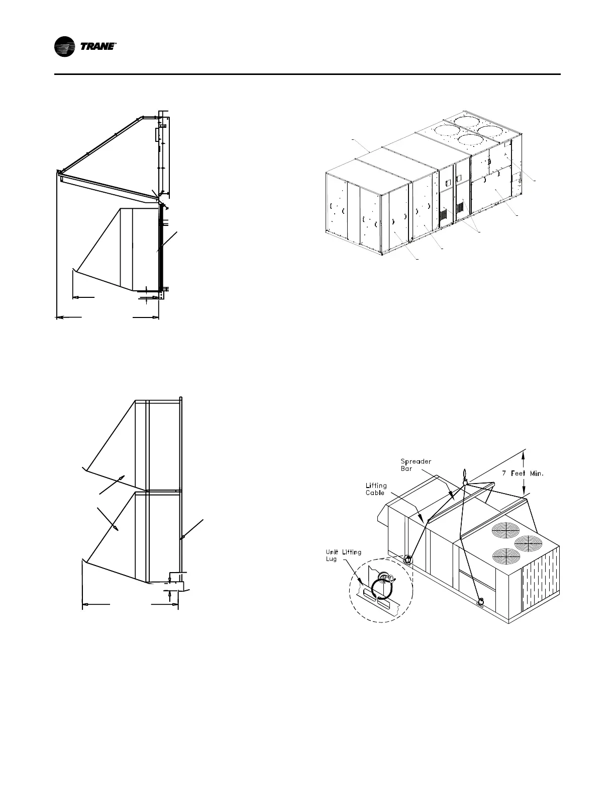
Figure 13. Side view showing fresh air and power
exhaust hoods for downflow return
32 1/8"
(814)
2 7/16"
(62)
37 3/4"
(959)
Fresh Air
Hood
End of
Unit
Pow er
Exhaust
Hood
Figure 14. Side view showing power exhaust hoods
for horizontal return
Pow er
Exhaust
Hoods
End of
Unit
32 1/8”
(814)
2 7/16”
(62)
Note: The two horizontal power exhaust hoods and the
three horizontal fresh air hoods are located side by
side. The fresh air hoods (not shown) extend only 23
15/16” from the end of the unit.
Figure 15. Location of “Ship With” items for TC*, TE*,
and YC* units
FILTER ACCESS
SUPPLY FAN
Ship with items are located
in supply fan section
HEATER ACCESS
COMPRESSOR ACCESS
CONTROL PANEL
VFD ACCESS
Unit Rigging and Placement
Use spreader bars as shown in the diagram. Refer to the
Installation manual or nameplate for unit weight. Refer to
the Installation instructions located inside the control panel
for further rigging information.
Verify that the roof curb has the proper gaskets installed
and is level and square to assure an adequate curb-to-unit
seal.
The units must be as level as possible in order to assure
proper condensate flow out of the unit. The maximum side-
to-side and end-to-end slope allowable in any application is
listed in Table 2, p. 19.
Figure 16. Unit rigging
Unit Dimensions and Weights