RT-SVX34V-EN
19
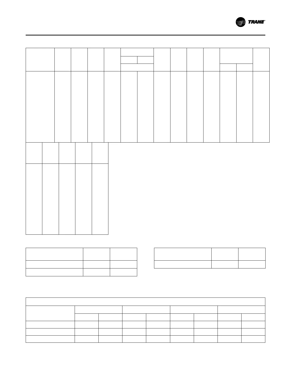
Table 1. Minimum operating clearances installation (horizontal, downflow, and mixed airflow configurations)
Unit Model
(60Hz/50Hz)
Baro.
Relief
Power
Exhaust
0-25%
Man
Damper
Econ.
Var. Freq. Drives
(VFD’s)
Serv.
Valves
Thru-the
base
Elec.
Non-
Fused
Discon.
Switch
Factory
GFI with
Discon.
Switch
Roof Curb
HGRH
Coil
W/O With
Bypass
Lo Hi
**(D,F)330/275
110/50 167/76 50/23 260/117 108/49 114/52 18/8 6/3 30/14 85/38 310/141 330/150 107/49
**(H,R)330/275
145/65 191/87 50/23 285/128 108/49 114/52 18/8 6/3 30/14 85/38 310/141 330/150 107/49
**(D,F)360/305
110/50 167/76 50/23 260/117 108/49 114/52 18/8 6/3 30/14 85/38 310/141 330/150 107/49
**(H,R)360/305
145/65 191/87 50/23 285/128 108/49 114/52 18/8 6/3 30/14 85/38 310/141 330/150 107/49
**(D,F)420/350
110/50 167/76 50/23 260/117 108/49 114/52 18/8 6/3 30/14 85/38 310/141 330/150 107/49
**(H,R)420/350
145/65 191/87 50/23 285/128 108/49 114/52 18/8 6/3 30/14 85/38 310/141 330/150 107/49
**(D,F)480/400
110/50 167/76 50/23 290/131 150/68 158/72 18/8 6/3 30/14 85/38 365/169 365/169 112/51
**(H,R)480/400
145/65 191/87 50/23 300/135 150/68 158/72 18/8 6/3 30/14 85/38 365/169 365/169 112/51
**(D,F)600/500
110/50 167/76 50/23 290/131 150/68 158/72 18/8 6/3 30/14 85/38 365/169 365/169 112/51
**(H,R)600/500
145/65 191/87 50/23 300/135 150/68 158/72 18/8 6/3 30/14 85/38 365/169 365/169 112/51
Con-
denser
Hail
Guards
Ultra
Low
Leak
Econ
Ultra
Low
Leak
50%
Exhaust
Ultra
Low
Leak
100%
Exhaust
eStage,
High
Efficien-
cy
105/48 112/51 34 / 15 74 / 34 251/114
105/48 78/35 34 / 15 77 / 35 251/114
105/48 112/51 34 / 15 74 / 34 251/114
105/48 78 /35 34 / 15 77 / 35 251/114
105/48 112/51 34 / 15 74 / 34 175/79
105/48 78/35 34 / 15 77 / 35 175/79
130/59 114/52 34 / 15 74 / 34 196/89
130/59 100/45 34 / 15 84 / 38 196/89
130/59 114/52 34 / 15 74 / 34 70/32
130/59 100/45 34 / 15 84 / 38 70/32
Table 2. Maximum slope
Cabinet
End to End
(inches)
Side to Side
(inches)
“A” (27.5 - 35 Ton Low Heat)
3 1/2 1 5/8
“B” (27.5 - 35 Ton High Heat)
4 1 5/8
Table 2. Maximum slope (continued)
Cabinet
End to End
(inches)
Side to Side
(inches)
“C” (All 40 and 50 Ton Units)
4 1/2 1 5/8
Note: Do not exceed these allowances. Correct the improper slope by
building up the curb base. The material used to raise the base must
be adequate to support both the curb and the unit weight.
Table 3. Center of gravity
Center-of-Gravity (inches)
Unit (60Hz)
TC TE YC Low
YC High
X Y X Y X Y X Y
27.5 Tons 91.0 40.8 91.1 41.0 91.3 40.2 102.9 40.1
30 Tons 91.2 40.9 91.4 41.0 91.5 40.3 103.1 40.1
35 Tons 91.9 41.1 92.0 41.3 92.2 40.5 103.7 40.4
Unit Dimensions and Weights