54
RT-SVX34V-EN
Table 26. 40 - 50 Ton horizontal economizer (O/A) damper static pressure setup (continued)
System
Design CFM
Return Air Duct Static + Return Air Damper Static (Inches of Water)
0.2 0.4 0.6 0.8 1 1.2 1.4
Drive Rod Position
21000 A A A A A B D
21500 A A A A A B D
22000 A A A A A A B
Models with Ultra-Low Leak Economizers
The installer can adjust the stroke of the direct drive
actuator on the O/A damper to compensate for various R/A
duct losses. Figure 43, p. 54 and Figure 44, p. 55 illustrate
the damper & actuator assembly and through list the
various O/A actuator limit positions based on the air flow
(CFM) and the return duct losses (static pressure) for
Downflow and Horizontal units. The actuator stroke limit
can be adjusted between 33% and 100% of full stroke. To
adjust the O/A damper for the correct pressure drop:
1. Measure the return duct static pressure.
2. Enter the calculated CFM from the previous section
“Verifying Proper Air Flow (CFM),” p. 42 to obtain the
return air damper pressure drop.
3. Add the measured return duct static pressure and the
return air damper pressure drop together to obtain the
Total Return Static Pressure. Apply this calculation and
the calculated CFM to the appropriate table. See
through .
4. To set the actuator stroke limit:
a. Loosen the screw that secures the angle of rotation
limiter on the actuator adjacent to the damper drive
shaft clamp.
b. Move the limiter to the desired % open position and,
making sure the limiter teeth are engaged, retighten
the screw. (See Figure 42, p. 54).
5. After setting the end stop, the actuator needs to be
cycled through its auto-adapt feature to re-scale the
control range. With 24 VAC power applied to the
actuator, turn the control signal reversing switch
forward and back again two times. Within a few
seconds, the actuator will cycle itself to the new limiter
position and then back to zero. This process may take
up to 5 minutes. The actuator will then be set to
respond to the 2-10 VDC control signal to cycle within
the new range of rotation set by the limiter. Verify that
the control signal reversing switch is set back to its
original default position - Y = 0 - same direction as
spring return. (See Figure 45, p. 55).
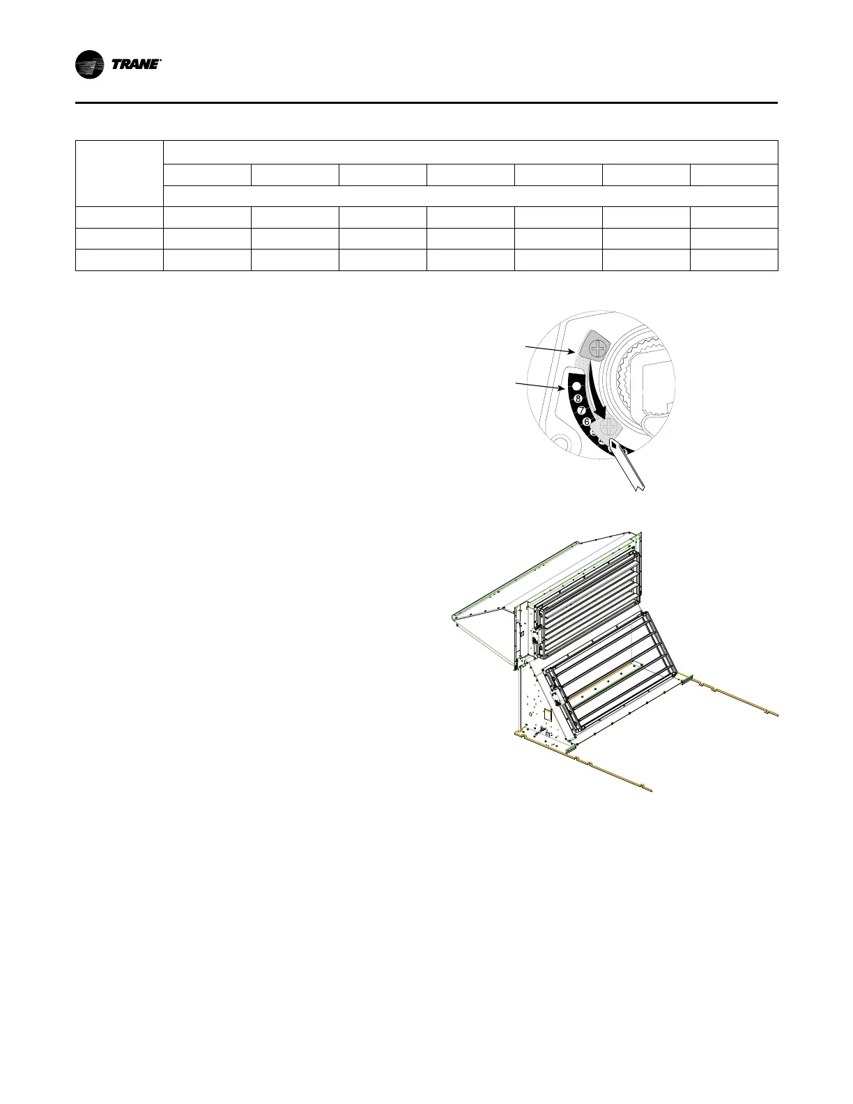
Figure 42. Actuator stroke limit adjustment
9
Philips screwdriver
Angle of Rotation
Limiter
Scale Shows % of
Full Stroke
Figure 43. Actuator for OA damper - Downflow
Startup