82
RT-SVX34V-EN
Note: Refrigerant oil is detrimental to some roofing
materials. Care must be taken to protect the roof
from oil leaks or spills.
Charge the new oil into the Schrader valve on the shell of
the compressor. Due to the moisture absorption properties
of POE oil, do not use POE oil from a previously opened
container. Also discard any excess oil from the container
that is not used.
Compressor model
Oil amount
CSHD075-161
7.0 pts
CSHD183
7.6 pts
Compressor Replacements
Electrical Phasing
If it becomes necessary to replace a compressor, it is very
important to review and follow the Electrical Phasing
procedure described in the startup procedure of this
manual.
If the compressors are allowed to run backward for even a
very short period of time, internal compressor damage may
occur and compressor life may be reduced. If allowed to
run backwards for an extended period of time the motor
windings can overheat and cause the motor winding
thermostats to open. This will cause a “compressor trip”
diagnostic and stop the compressor.
If a scroll compressor is rotating backwards, it will not pump
and a loud rattling sound can be observed. Check the
electrical phasing at the compressor terminal box. If the
phasing is correct, before condemning the compressor,
interchange any two leads to check the internal motor
phasing.
Precision Suction Restrictor
Manifolded compressors that have unequal capacity sizes
use a precision suction restrictor to balance the oil levels in
the compressors (see figure below). This restrictor is
placed in the smaller capacity compressor. When replacing
this compressor, it is imperative that the proper restrictor is
selected from those provided with the replacement
compressor.
When the compressors are restarted, verify that correct oil
levels are obtained with both compressors operating.
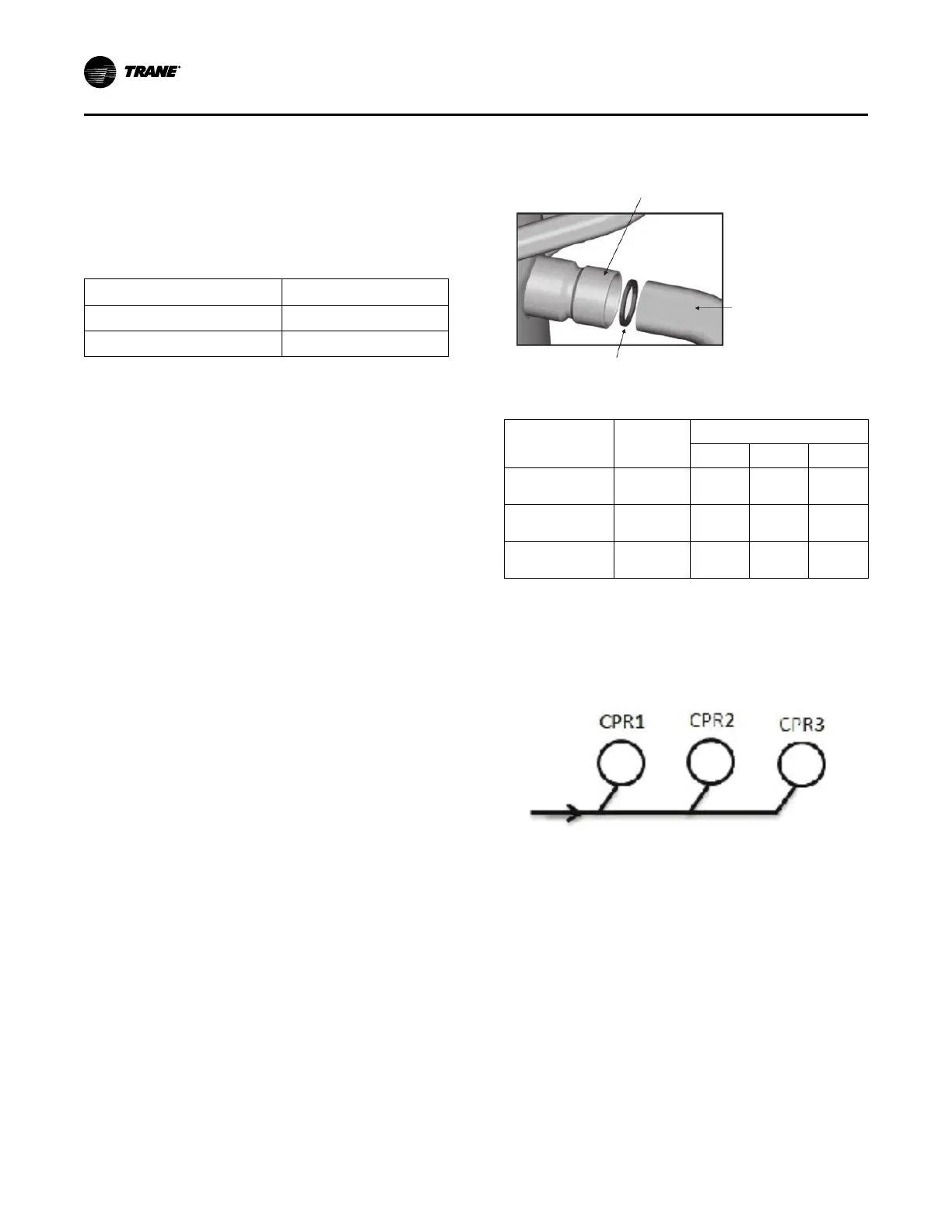
Figure 69. Precision suction restrictor
Compressor
Suction
Suction
Tube
Suction Restrictor
Table 38. Compressor restrictor location
Model
Efficiency
Restrictor Location
CPR 1 CPR2 CPR 3
TC/TE/YC*275 and
330
High and
Std
X
TC/TE/YC*305 and
360
High and
Std
X
TC/TE/YC*500 and
600
High and
Std
X
Figure 70. Compressors
27.5-50 Tons Standard and
High Eciency
VFD Programming Parameters
(Supply)
Units shipped with an optional variable frequency drive
(VFD) are preset and run tested at the factory. If a problem
with a VFD occurs, ensure that the programmed
parameters listed in Table 39, p. 84 have been set before
replacing the drive.
Verify Parameters
Verify parameter 1-23 is set to 60 Hz (or 50 Hz where
applicable) and that parameter 0-06 is set to the correct
supply voltage/frequency range.
1. To check parameter 1-23 press the Main Menu button
twice (if TR150 drive) (press the Back button if the main
Maintenance