84
RT-SVX34V-EN
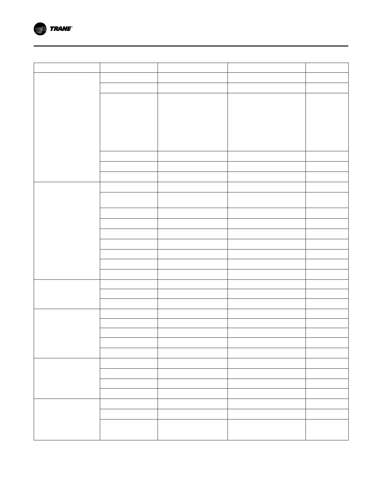
Table 39. Relief/return fan VFD parameters
Menu ID Name FC Unit
Operation/Display
0-01
Language English US
0-03
Regional Settings
North America
0-06 (TR150 only) Grid Type
Set to applicable unit power supply
200-240V/60Hz for 200 & 230V/60Hz
units; 440-480V/60Hz for 460V/60Hz
units; 525-600V/60Hz for 575V/60Hz
units; 380-440V/50Hz for 380 &
415V/50Hz supply.For IT Grid (no
ground connections) or corner-
grounded Delta power supply
systems, select the applicable
voltage/Hz and IT-Grid or Delta.
0-20 (TR200 only) Display Line 1.1 Small Analog Input 53
0-22 (TR200 only) Display Line 1.3 Small Input Power [hp]
0-40
[Hand on] Key on LCP
Disabled
Load and Motor
1-03
Torque Characteristics Variable Torque
1-20 (TR150)1-21
(TR200)
Motor Power [HP] Per Motor Nameplate HP hp
1-22
Motor Voltage Per Motor Nameplate Voltage
V
1-23
Motor Frequency Per Motor Nameplate
Hz
1-24 Motor Current
Per Motor Nameplate FLA
A
1-25
Motor Nominal Speed Per Motor Nameplate Rated Speed
RPM
1-39 Motor Poles 4
1-73
Flying Start
Enabled
1-90 Motor Thermal Protection
ETR Trip1
Brakes
2-00 DC Hold/Preheat Current 0 %
2-01 DC Brake Current 0 %
2-04
DC Brake Cut In Speed [Hz]
10 Hz
Reference / Ramps
3-03 Maximum Reference 60 Hz
3-16 Reference 2 Source No function
3-17 Reference 3 Source No function
3-41
Ramp 1 Ramp up Time
30 s
3-42
Ramp 1 Ramp Down Time
30 s
Limits / Warnings
4-12
Motor Speed Low Limit [Hz]
35 Hz
4-14
Motor Speed High Limit [Hz]
60 Hz
4-18 Current Limit 100 %
4-19
Max Output Frequency
60 Hz
Digital In/Out
5-12
Terminal 27 Digital Input
Coast inverse
5-13
Terminal 29 Digital Input No operation
5-40
Function Relay
Relay 1 active No alarm, Relay 2
active Motor Running (Relay 1 [160],
Relay 2 [5])
Maintenance