58
RT-SVX34V-EN
Manual Outside Air Damper
Units ordered with the 25% manual outside air option have
two slidable dampers. By adjusting one or both, the desired
amount of fresh air entering the system can be obtained.
To adjust the outside air damper;
1. Turn the “System” selection switch to the “Off” position
and the “Fan” selection switch (if applicable) to the
“Auto” position.
2. Close the disconnect switch or circuit protector switch
that provides the supply power to the unit's power
terminal block or the unit factory mounted disconnect
switch.
WARNING
Live Electrical Components!
Failure to follow all electrical safety precautions when
exposed to live electrical components could result in
death or serious injury.
When it is necessary to work with live electrical
components, have a qualified licensed electrician or
other individual who has been properly trained in
handling live electrical components perform these
tasks.
HIGH VOLTAGE IS PRESENT AT TERMINAL BLOCK
HTB1 OR UNIT DISCONNECT SWITCH.
3. Remove the mist eliminator retainer bracket and the
mist eliminators from the fresh air hood.
4. Remove the five (5) screws in the top and bottom of
each fresh air damper located inside the hood area.
5. Using the Symbio™ 700 user interface or the mobile
app, choose a Service Test Step for ventilation.
6. With the supply fan “On” and rotating in the proper
direction, measure the return duct static pressure.
7. Using Table 32, p. 58, enter the desired amount of
fresh air and the return air static pressure reading to
obtain the proper damper opening dimension.
8. Loosen the adjustment screws on each side of the
damper and slide it downward to the required opening.
9. Tighten the adjustment screws and re-install the mist
eliminators and the mist eliminator retainer bracket.
10. Open the main power disconnect or the unit mounted
disconnect switch to shut the unit off and to reset the
Symbio™ controls.
11. Before closing the disconnect switch, ensure that the
compressor discharge service valve(s) and suction
service valve(s) are backseated.
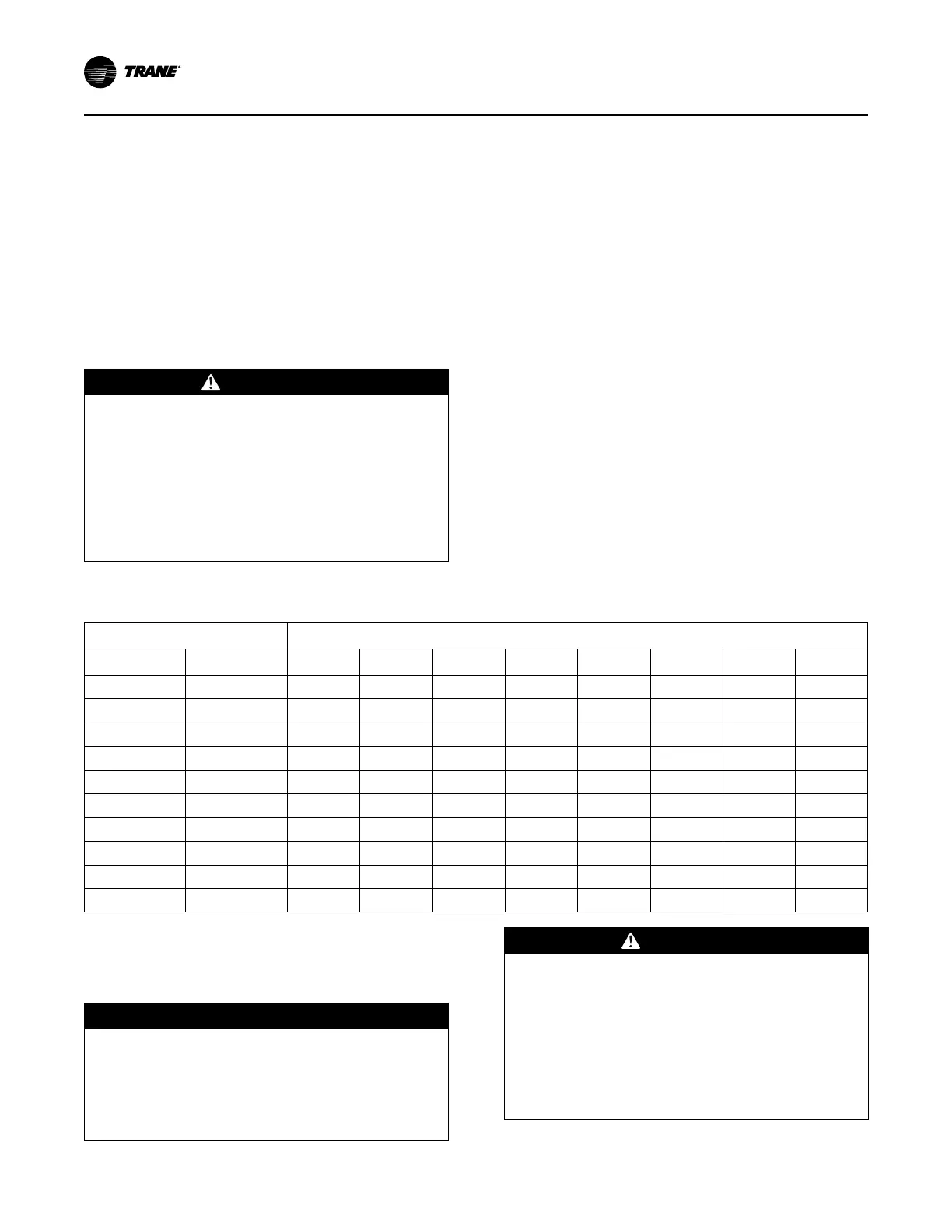
Table 32. Damper adjustment
Damper Opening (in.)
Return Air Static Pressure - Inches w.c.
Damper #1 Damper #2
-0.20 -0.40 -0.60 -0.80 -1.00 -1.20 -1.40 -1.60
2 0 430 590 725 840 950 1040 1120 740
4 0 780 1080 1330 1545 1730 1890 2035 2170
6 0 1185 1620 1990 2300 2575 2815 3030 3240
8 0 1530 2110 2600 3025 3390 3705 3985 4240
10 0 1930 2655 3270 3800 4250 4650 5005 5345
10 2 2295 3165 3910 4545 5095 5575 6010 6415
10 4 2660 3650 4510 5255 5905 6480 6995 7470
10 6 3010 4150 5130 5965 6690 7330 7900 8440
10 8 3345 4600 5680 6610 7410 8120 8765 9365
10 10 3690 5125 6350 7395 8295 9075 9775 10420
Starting the Compressor
Optional service valves must be fully opened before startup
(suction and discharge line).
NOTICE
Compressor Failure!
Failure to follow instruction below could result in
compressor failure.
Unit must be powered and crankcase heaters
energized at least 8 hours BEFORE compressors are
started.
WARNING
Live Electrical Components!
Failure to follow all electrical safety precautions when
exposed to live electrical components could result in
death or serious injury.
When it is necessary to work with live electrical
components, have a qualified licensed electrician or
other individual who has been properly trained in
handling live electrical components perform these
tasks.
Startup