26
RT-SVX34V-EN
Installation Electrical
WARNING
Hazardous Voltage!
Failure to disconnect power before servicing could
result in death or serious injury.
Disconnect all electric power, including remote
disconnects before servicing. Follow proper lockout/
tagout procedures to ensure the power can not be
inadvertently energized. Verify that no power is
present with a voltmeter.
Disconnect Switch External
Handle (Factory Mounted
Option)
Units ordered with the factory mounted disconnect switch
come equipped with an externally mounted handle. This
allows the operator to disconnect power from the unit
without having to open the control panel door. The handle
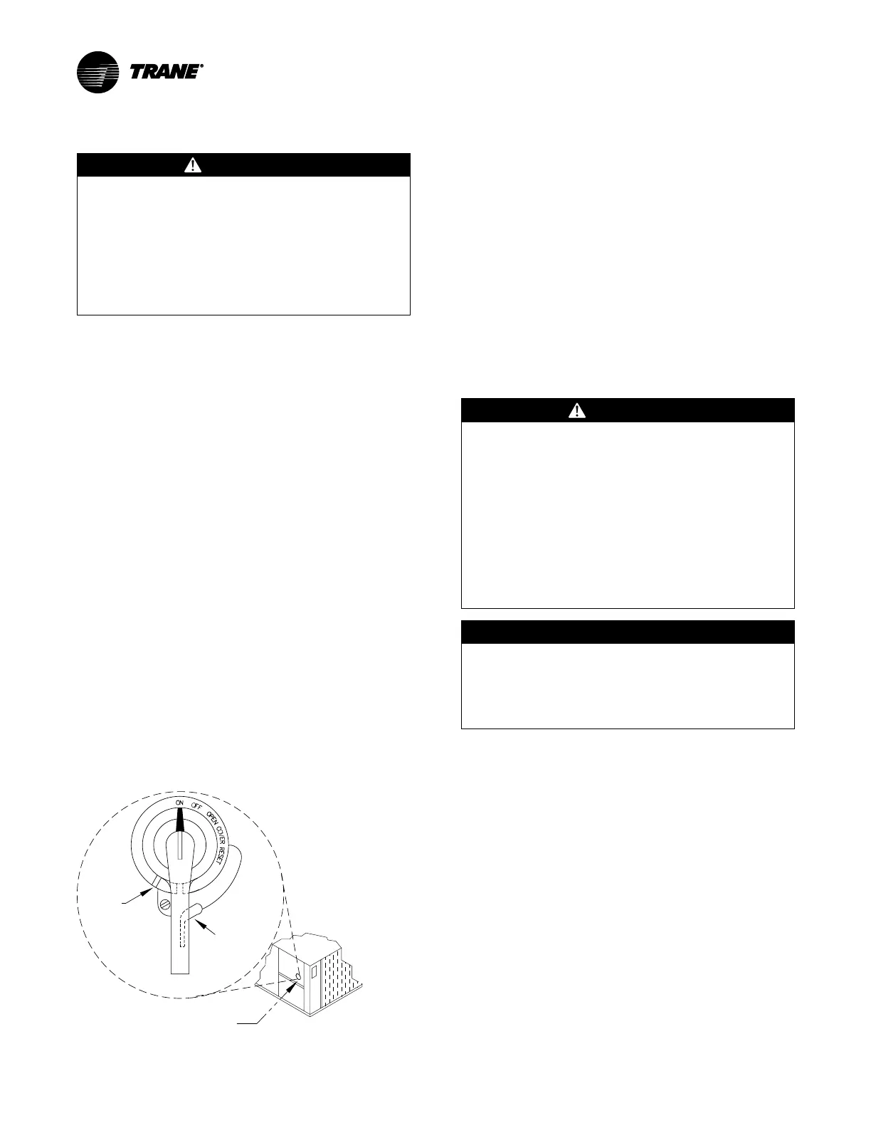
location and its three positions are shown below;
• ON - Indicates that the disconnect switch is closed,
allowing the main power supply to be applied at the
unit.
• OFF - Indicates that the disconnect switch is open,
interrupting the main power supply at the unit.
• OPEN COVER/RESET - Turning the handle to this
position releases the handle from the disconnect
switch, allowing the control panel door to be opened.
Once the door has been opened, it can be closed with the
handle in any one of the three positions outlined above,
provided it matches the disconnect switch position. The
handle can be locked in the “OFF” position. While holding
the handle in the “OFF” position, push the spring loaded
thumb key, attached to the handle, into the base slot. Place
the lock shackle between the handle and the thumb key.
This will prevent it from springing out of position.
Figure 22. Disconnect switch
Disconnect switch
external handle
Locking
slot (OFF)
Locking
thumb key
C
ontr
o
l
Pa
n
e
l
Compressor Panel
An overall layout of the field required power wiring is
illustrated in . To insure that the unit supply power wiring is
properly sized and installed, follow the guidelines outlined
below.
Note: All field installed wiring must conform to NEC
guidelines as well as State and Local codes.
Verify that the power supply available is compatible with
the unit's name plate ratings for all components. The
available power supply must be within 10% of the rated
voltage stamped on the nameplate. Use only copper
conductors to connect the 3-phase power supply to the
unit.
Main Power Wiring
WARNING
Proper Field Wiring and Grounding
Required!
Failure to follow code could result in death or serious
injury.
All field wiring MUST be performed by qualified
personnel. Improperly installed and grounded field
wiring poses FIRE and ELECTROCUTION hazards. To
avoid these hazards, you MUST follow requirements
for field wiring installation and grounding as
described in NEC and your local/state/national
electrical codes.
NOTICE
Use Copper Conductors Only!
Failure to use copper conductors could result in
equipment damage as the equipment was not
designed or qualified to accept other types of
conductors.
• Electrical service sizing data can be found on unit name
plate and in the product catalog. The electrical service
must be protected from over current and short circuit
conditions in accordance with NEC requirements.
Protection devices must be sized according to the
electrical data on the nameplate. Refer to “Electrical
Wire Sizing and Protection Device Equations,” p. 28 for
determining:
– The appropriate electrical service wire size based
on “Minimum Circuit Ampacity” (MCA),
– The “Maximum Over current Protection” (MOP)
device.
– The “Recommended Dual Element fuse size”
(RDE).
• If the unit is not equipped with an optional factory
installed Nonfused disconnect switch, a field supplied
disconnect switch must be installed at or near the unit
in accordance with the National Electrical Code (NEC