RT-SVX34V-EN
27
latest edition). Refer to DSS calculations “Electrical
Wire Sizing and Protection Device Equations,” p. 28 for
determining correct size.
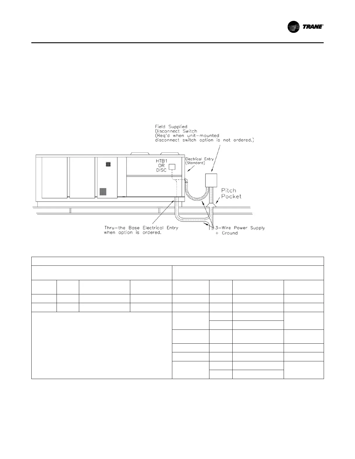
Location for the electrical service entrance is shown
in the unit dimensional drawings beginning with .
Complete the unit's power wiring connections onto
either the main terminal block HTB1, or the factory
mounted nonfused disconnect switch inside the unit
control panel.
Note: When the factory installed through-the-base
option is not used, the installing contractor is
required to seal any holes made in the base of
the unit to prevent water from leaking into the
building.
• Provide proper grounding for the unit in accordance
with local and national codes.
Figure 23. Typical field power wiring
Table 7. Customer connection wire range
CUSTOMER CONNECTION WIRE RANGE
UNITS WITH MAIN POWER TERMINAL BLOCK ( ALL VOLTAGES)
UNITS WITH MAIN POWER DISCONNECT SWITCH/ CIRCUIT BREAKER (ALL
VOLTAGES)
BLOCK
SIZE
WIRE
QTY
CONNECTION WIRE
RANGE
USAGE DISCONNECT
WIRE
QTY
CONNECTOR WIRE
RANGE
USAGE
335 AMP 1 # 6 AWG - 400 MCM X<= 335 & Z<= 125 100 AMP 1 14 AWG - 3/0 x <= 100 & z <= 95
420 AMP 1 # 2 AWG - 600 MCM X<= 420 & Z<= 230 250 AMP 1 4 AWG - 350 MCM 100 < x <= 250
x = Max(MCA, 1.15*Heating amps, 1.15*Cooling amps) z = Heater amps +
SF amps + EF amps
400 AMP
1 1 AWG- 600 MCM
250 < x <= 400
2 2 AWG- 250 MCM
CIRCUIT
BREAKER
WIRE
QTY
CONNECTOR WIRE
RANGE
USAGE
100 AMP 1 14 AWG - 3/0 x <= 100 & z <= 95
250 AMP 1 4 AWG - 350 MCM 100 < x <= 250
400 AMP
1 1 AWG- 600 MCM
250 < x <= 400
2 2 AWG- 250 MCM
Installation Electrical