RT-SVX34V-EN
23
Installation General Requirements
Condensate Drain Connection
Each commercial rooftop unit is equipped with one (1) 1-1/
4 inch Female NPT (threaded) drain connection.
Refer to “Unit Dimensions and Weights,” p. 11 for the
location of the connector. A condensate trap must be
installed due to the drain connection being on the “negative
pressure” side of the fan. Install a P-Trap at the unit using
the guidelines in Figure 18, p. 23.
Pitch the drain line at least 1/2 inch for every 10 feet of
horizontal run to assure proper condensate flow.
Ensure that all condensate drain line installations comply
with applicable building and waste disposal codes.
Notes:
• For units with optional Condensate Overflow
Switch (COF), the switch will not work properly
if unit is not level or slightly sloped toward
switch.
• To ensure proper condensate flow during
operation the unit and the curb must be level.
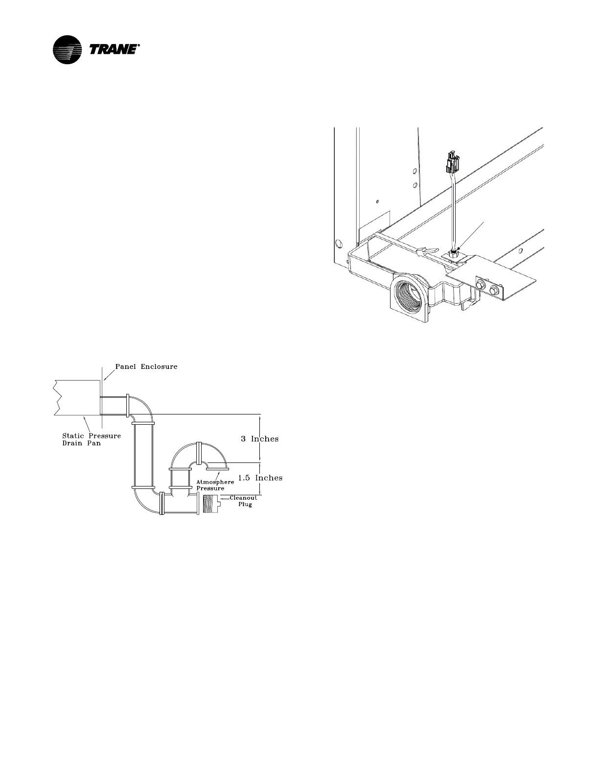
Figure 18. Condensate trap installation
Condensate Overflow Switch
This switch protects building from condensate overflow
damage. It is factory-installed and tested.
Figure 19. Condensate overflow switch location
O/A Sensor and Tubing
Installation
An Outside Air Pressure Sensor is shipped with all units
designed to operate on traditional variable air volume
applications (non-SZ VAV) and units with Statitrac™.
A duct pressure transducer and the outside air sensor is
used to control the discharge duct static pressure to within
a customer-specified controlband. Refer to the illustration
in Figure 20, p. 24 and the following steps to install the
sensor and the pneumatic tubing.
1. Remove the O/A pressure sensor kit located inside the
fan section. The kit contains the following items;
• an O/A static pressure sensor
• a sensor mounting bracket
• 50’ of 3/16” O.D. pneumatic tubing
• mounting hardware
2. Using two #10-32 x 1-3/4” screws provided, install the
sensor's mounting bracket to the factory provided
bracket (near the fan section).
3. Using the #10-32 x 1/2” screws provided, install the O/A
static pressure sensor vertically to the sensor bracket.
4. Remove the dust cap from the tubing connector located
below the sensor in the vertical support.
5. Attach one end of the 50' x 3/16” O.D. factory provided
pneumatic tubing to the sensor's top port, and the other
end of the tubing to the connector in the vertical
support. Discard any excess tubing.