EasyManua.ls Logo

Trane Technologies BAYSTAT152A - User Manual

Trane Technologies BAYSTAT152A
56 pages
Print Icon
To Next Page IconTo Next Page
Loading...
Touch-screen Programmable
Thermostat
Installation, Operation, and Maintenance
June 2022
BAS-SVX44C-EN
Trane Part Number:
X13511538-01
Clarksville Part Number:
BAYSTAT152A
Service Part Number:
THT02775
SAFETY WARNING
Only qualified personnel should install and service the equipment. The installation, starting up, and servicing of
heating, ventilating, and air-conditioning equipment can be hazardous and requires specific knowledge and training.
Improperly installed, adjusted or altered equipment by an unqualified person could result in death or serious injury.
When working on the equipment, observe all precautions in the literature and on the tags, stickers, and labels that are
attached to the equipment.

Table of Contents

Questions and Answers

  • D
    David BeardAug 16, 2025
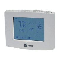
    What to do if my Trane Technologies Thermostat flashes '--F' or '--C'?
    • T
      tony75Aug 17, 2025
      If the Trane Technologies Thermostat displays “--F” or “--C” flashes, it means the temperature is outside of the measurable range. If using a remote temperature sensor, ensure the temperature is within the measurable range and check or replace the sensor. If using a local temperature reading, and the temperature is within range, have the thermostat serviced or replaced by a qualified Trane supplier.
  • A
    Allen ConleyAug 22, 2025
    What to do if Trane Technologies Thermostat shows error code E1 or flashing humidity display?
    • C
      Cheryl BestAug 22, 2025
      If your Trane Technologies Thermostat shows error code E1 or “--” flashing in the humidity display, it indicates that the humidity reading is outside of the measurable range or there is an error with the humidity sensor. For an internal humidity sensor, try power cycling the thermostat. For an external sensor, check the Hs and Hp terminals and ensure the remote humidity sensor is not damaged; replace it if needed. If the issue persists, have the thermostat serviced or replaced by a qualified Trane supplier.
  • E
    Edward WatsonAug 25, 2025
    How to fix error code E5 on Trane Technologies BAYSTAT152A Thermostat?
    • M
      mpearsonAug 26, 2025
      If your Trane Technologies Thermostat displays error code E5, which indicates an issue with the RTC (Real Time Clock), first set the clock from the Home screen. If that doesn't work, try power cycling the unit. If the error persists, have the thermostat serviced or replaced by a qualified Trane supplier.
  • C
    Craig WhiteAug 27, 2025
    Why is the display blank on my Trane Technologies Thermostat?
    • C
      Cheryl SmithAug 28, 2025
      If the Trane Technologies Thermostat display is blank, check the power supply to the thermostat. If the power supply is working correctly, have the thermostat serviced or replaced by a qualified Trane supplier.
  • B
    Brian HigginsAug 30, 2025
    What does error code E4 mean on a Trane Technologies BAYSTAT152A Thermostat?
    • R
      Richard MartinezAug 30, 2025
      If the Trane Technologies Thermostat shows error code E4, indicating that the input voltage is out of range, check the input voltage to the thermostat. It must be within the range of 18 Vac to 32 Vac RMS.
  • L
    lthomasSep 2, 2025
    What to do if relays do not turn ON in Trane Technologies BAYSTAT152A Thermostat?
    • W
      watsonkristenSep 2, 2025
      If the Trane Technologies Thermostat's relays do not turn ON, use Test Modes 1–6 to toggle the relay(s) in question. If the relay(s) do not toggle in test mode, have the thermostat serviced or replaced by a qualified Trane supplier.
  • M
    Marcus BarnesSep 4, 2025
    Why are the fan settings not visible on my Trane Technologies Thermostat?
    • E
      Erin JamesSep 5, 2025
      If you're unable to see the fan settings on your Trane Technologies Thermostat, first check the system status. If the system is OFF, the fan settings will not appear. Also, check Configuration Option Numbers 0130 and 0151 to verify that the fan is enabled.
  • M
    Margaret JonesSep 7, 2025
    What does error code E0 mean on a Trane Technologies Thermostat?
    • A
      Andre McdowellSep 8, 2025
      If your Trane Technologies Thermostat displays error code E0, which is a thermistor error, and if configuration option #210 is set to 1, 2, 3, or 4, check the sensor terminals S1 and S2 for a secure connection. If the wires are securely connected, try replacing the sensor. If the error persists, have the thermostat serviced or replaced by a qualified Trane supplier.
  • K
    kelly39Sep 10, 2025
    Why does the display screen on my Trane Technologies BAYSTAT152A Thermostat not respond?
    • K
      Kimberly OconnorSep 12, 2025
      If the Trane Technologies Thermostat display screen does not respond, first ensure that the thermostat modes are not locked. If they are not, cycle the power to the thermostat. You can also run Test #8 to confirm touch response. If the screen is not locked and cycling the power does not solve the problem, have the thermostat serviced or replaced by a qualified Trane supplier.
  • L
    Linda MillerSep 12, 2025
    Why is the display erratic on my Trane Technologies Thermostat?
    • K
      Kevin JohnstonSep 12, 2025
      If the display appearance or contrast on your Trane Technologies Thermostat is erratic, check the power supply (24 Vac nominal) and frequency setting (Configuration Option Number 0170). You can also try cycling the power to the thermostat. After verifying the power supply and frequency setting, have the thermostat serviced or replaced by a qualified Trane supplier.

Summary

Installation, Operation, and Maintenance

Touch-screen Programmable Thermostat

This document details the installation, operation, and maintenance of the Trane touch-screen programmable thermostat.

Safety Warning

Crucial safety precautions and hazard information for installation and servicing of HVAC equipment.

Introduction

Warnings, Cautions, and Notices

Definitions of the types of advisories used in the manual: WARNING, CAUTION, and NOTICE.

Copyright and Trademarks

Information regarding document ownership, reproduction rights, and registered trademarks.

Overview

Manual Contents

An overview listing the topics and sections covered within the installation manual.

Packaged Contents and Tools

Packaged Contents

A list of all items included in the thermostat packaging, such as the unit and accessories.

Tools Required

A list of tools necessary for the proper installation and setup of the thermostat.

Specifications and Dimensions

Technical Specifications

Detailed operating ranges, power requirements, and performance specifications.

Physical Dimensions

Measurements and diagrams illustrating the physical size of the thermostat unit.

Product Features and Functions

Key Features

Highlights the thermostat's LCD touch screen, system modes (Heat, Cool, Auto), and fan modes.

Additional Functions

Lists extended features like scheduling, temperature cycling, and system lockout.

Pre-Installation Requirements

Location Considerations

Guidance on selecting an installation site to ensure accurate temperature sensing.

Height Requirements

Recommendations for the optimal vertical mounting height of the thermostat.

Mounting Surfaces

Information on suitable surfaces and methods for securely mounting the thermostat.

Maximum Wire Length

Limits on wire gauge and length to ensure proper thermostat communication.

Installation and Wiring

Thermostat Mounting and Cover Removal

Steps for physically attaching the thermostat and safely removing its front cover.

Mounting the Backplate

Securing the thermostat's mounting plate to the wall.

Wiring and Wiring Diagrams

Instructions and illustrations for making electrical connections to the thermostat.

Terminal Identification

Descriptions of each terminal on the thermostat and its function.

Thermostat Cover Replacement

Procedure for reattaching the thermostat's front cover after wiring.

Power, System Tests, and Software Reset

Applying Power

Steps to restore electrical power to the thermostat and connected HVAC system.

Power-up Test

Description of the automatic diagnostic test performed upon startup.

System Tests

Procedures for manually running diagnostic tests to verify thermostat functionality.

Software Reset

Explanation of how to reboot the thermostat and restore default software settings.

Configuration Option Setup

Activating Setup Mode

Instructions for accessing the thermostat's configuration and setup menus.

Installer Configuration Setup Menu

A list of configurable options with their defaults, values, and descriptions.

Installer Configuration Setup Menu (Continued)

Continuation of the configuration options list, detailing various settings.

Installer Configuration Setup Menu (Continued)

Final part of the configuration options list, detailing various settings.

Operation

Thermostat Icon Descriptions

An explanation of the various icons displayed on the thermostat's screen.

Functions

Time Setup

Guide for setting or adjusting the thermostat's internal clock.

Dehumidify Setup

Instructions for configuring the dehumidification level and settings.

System Mode Setup

How to select and change the operating mode (Heat, Cool, Auto, Off).

Fan Mode

Instructions for setting the fan operation to Auto or continuous On.

Temporary Override (TOV) Setup

How to temporarily adjust setpoints or fan settings outside the schedule.

Schedule Setup

Overview of how to program daily heating and cooling schedules.

Schedule Display Mode

Method for viewing the currently programmed thermostat schedule.

Day;Period;Time Schedule Change Mode

Procedure for modifying schedule times, periods, and days.

Setpoint;Fan Schedule Change Mode

Procedure for modifying schedule setpoints and fan settings.

General Notes for All Schedule Modes

Important considerations and variations for different schedule programming modes.

Default Settings and Worksheet

Provides default schedule parameters and space for custom settings.

Other Thermostat Functions

Heat;Cool Indicator Display

How the thermostat visually indicates current heating or cooling activity.

Non-programmable Mode

Description of thermostat functions when configured as non-programmable.

Filter Change

Procedure for resetting the filter replacement indicator light.

Clean Screen

Instructions for safely cleaning the thermostat's touch screen display.

Local;Remote;Outdoor Temperature Display and Control

Managing temperature readings from internal, remote, or outdoor sensors.

Local;Remote Humidity Display and Control

Managing humidity readings from internal or remote sensors.

System Lockout

How to enable or disable access to thermostat settings to prevent tampering.

Temperature Cycle Control

Heat;Cool Cycling Rates

Explanation of cycles per hour (CPH) and duty cycle for HVAC operation.

Auto Heat and Cool Systems

Cycling control logic for single-stage auto heat and cool systems.

Auto 3;heat and 2;cool Systems

Cycling control logic for three-stage heat and two-stage cool systems.

Other Functional Components

Sleep Mode

Information on the thermostat's low-power state when inactive.

Changeover Operation

How the thermostat automatically switches between heating and cooling modes.

Extension of Fan-on Time

How to extend the duration of the fan operation in heating or cooling.

Economizer;Time of Day (TOD)

Setting options for Economizer or Time of Day (TOD) control.

Configuration, Time, and Programming Retention

How settings, time, and schedules are stored and retained during power loss.

Heat;Cool Relay Confirmation

Logic for setting/resetting relays to prevent incorrect switching.

Deadband

The temperature range around setpoints that controls system cycling.

Temperature Display Offset

Adjusting the displayed temperature to match actual room conditions.

Humidity Display Offset

Adjusting the displayed humidity to match actual room conditions.

LCD Backlight

Settings and behavior of the thermostat's display backlight.

Compressor Protection

Measures to prevent damage to the compressor from rapid cycling.

Permanent Memory Data

How thermostat configuration and schedule data is stored.

Compressor and Auxiliary Heat Lockout

Conditions under which compressor or auxiliary heat operates.

Error Codes and Exceptions

Error Codes

A list and explanation of error codes that may appear on the thermostat display.

Exceptions

Description of how the thermostat handles abnormal operating conditions.

Troubleshooting

Problem Diagnosis and Solutions

A troubleshooting table to help identify and resolve common thermostat issues.

Trane Technologies BAYSTAT152A Specifications

General IconGeneral
BrandTrane Technologies
ModelBAYSTAT152A
CategoryThermostat
LanguageEnglish