32
CVHE-SVX005B-EN
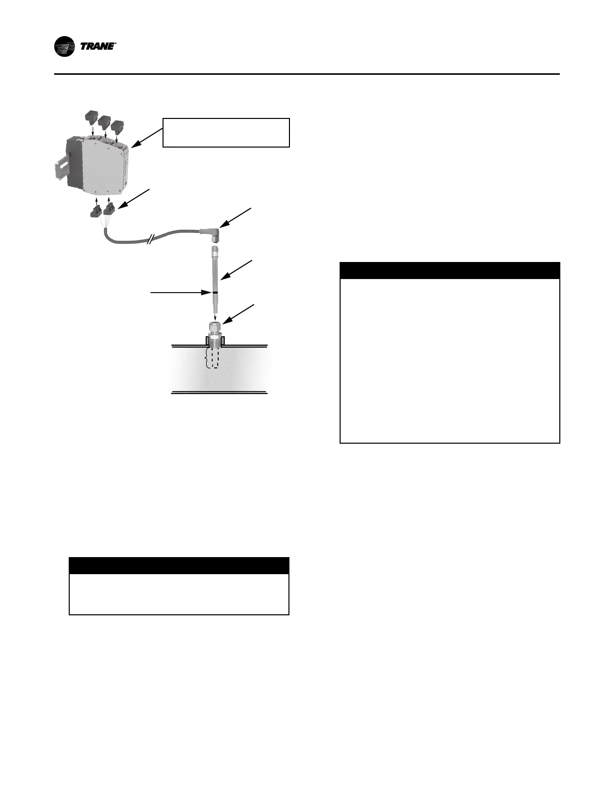
Figure 11. Installation of ifm efector flow detection
controller and sensor
If factory-provided,
located in control panel.
Do NOT insert more than
3.5 in. (8.9 cm) of the
probe length into the pipe.
4
3
2
1
Use a marker to draw a line
on the probe at 3.5 in. (8.9 cm)
from the probe end.
1. Mount the 1/2-in. NPT adapter in a horizontal or
vertical section of pipe. The maximum distance
from the control panel must not exceed 29.5 ft (9 m)
(see item labeled “1” in the preceding figure). Allow
at least five pipe diameters straight run of pipe
upstream of the sensor location, and three pipe
diameters straight run of pipe downstream of the
sensor location.
NNoottee:: In the case of a horizontal pipe, mounting the
sensor in the side of the pipe is preferred. In
the case of a vertical pipe, mounting the
sensor in a place where the water flows
upwards is preferred.
NNOOTTIICCEE
OOvveerrttiigghhtteenniinngg!!
DDoo nnoott eexxcceeeedd ttoorrqquuee ssppeecciiffiiccaattiioonnss aass iitt ccoouulldd
rreessuulltt iinn eeqquuiippmmeenntt ddaammaaggee..
2. Insert the flow sensor probe (see item labeled “2”
in the preceding figure) through the 1/2-in. NPT
adapter so that 3 to 3.5 in. (7.6 to 8.9 cm) of the
probe’s length extends into the pipe. Tighten the 1/
2-in. NPT adapter as needed to prevent leakage and
keep the probe from backing out under pressure.
DDoo NNOOTT eexxcceeeedd 4400 fftt··llbb ((5544..22 NN··mm)) ooff ttoorrqquuee oonn
tthhee ffiittttiinngg.. SSeennssoorr ddaammaaggee ccaann ooccccuurr iiff iitt iiss
oovveerrttiigghhtteenneedd..
NNoottee:: When installed, the tip of the ifm efector
®
sensor probe must be at least 1 in. (2.54 cm)
away from any pipe wall. Do NOT insert more
than 3.5 in. (8.9 cm) of the probe length into
the pipe.
3. Install the Micro DC Cable by inserting it through
the wire openings on the back side of the control
panel (see item labeled “3” in the preceding figure).
Install the supplied Micro DC Cable (29.5 ft [9 m] in
length) to the Flow Probe and hand-tighten the
connector nut.
4. Plug the other end of the Micro DC Cable into the
Flow Control Monitor with the Combicon connector
(see item labeled “4” in the preceding figure). Refer
to the following figure for cable wiring.
NNOOTTIICCEE
DDoo NNoott AAppppllyy EElleeccttrriiccaall PPoowweerr ttoo aa
UUnniitt iinn aa VVaaccuuuumm!!
FFaaiilluurree ttoo ffoollllooww iinnssttrruuccttiioonnss bbeellooww ccoouulldd
rreessuulltt iinn mmoottoorr aanndd ccoommpprreessssoorr ddaammaaggee..
DDoo nnoott aappppllyy eelleeccttrriiccaall ppoowweerr ttoo aa mmoottoorr iinn aa
vvaaccuuuumm..
FFoorr uunniittss wwiitthh iinnssiiddee--tthhee--ddeellttaa ssoolliidd ssttaattee
ssttaarrtteerrss,, ddiissccoonnnneecctt ppoowweerr ttoo uunniitt dduurriinngg
eevvaaccuuaattiioonn oorr wwhheenn tthhee uunniitt iiss iinn aa ddeeeepp
vvaaccuuuumm.. IInn aaddddiittiioonn,, oonn uunniittss wwiitthh iinnssiiddee--tthhee--
ddeellttaa ssoolliidd ssttaattee ssttaarrtteerrss,, aallll ppoowweerr ttoo tthhee uunniitt
mmuusstt bbee ddiissccoonnnneecctteedd pprriioorr ttoo eevvaaccuuaattiinngg tthhee
uunniitt aass lliinnee ppoowweerr iiss ddiirreeccttllyy aapppplliieedd ttoo tthhee
mmoottoorr tteerrmmiinnaallss 44,, 55,, aanndd 66..
5. Apply power to the chiller control panel to verify the
Flow Control Monitor has power and the Low Volt
Broken Wire Relay light is NOT lit.
6. Remove all air from the piping circuit prior to
adjusting the low water flow setpoint.
7. Reduce the water flow to the minimum allowable
flow and adjust the Flow setting on the Flow
Control Monitor (see item labeled “7” in the
following figure). Adjusting the “Flow”
potentiometer clockwise (+) reduces the flow
setting cutout and adjusting counterclockwise (-)
increases the flow setting cutout.
NNoottee:: The “Temp” potentiometer on the ifm
efector
®
control module has no effect in
Trane application. It is NOT necessary to
make adjustments to the “Temp”
potentiometer.
8. After the cutout setting is adjusted, the cutout
setpoint will be indicated with a yellow light on the
Flow Control Monitor LED bar graph display. When
the water flows are higher than the cutout, a green
light will indicate proper flow status. If the flows fall
below the cutout setpoint, a red light will indicate
low/no flow status.
IInnssttaallllaattiioonn:: WWaatteerr PPiippiinngg