CVHE-SVX005B-EN
37
section locating into the groove.
5. Insert a standard hex head screw through the
mating holes of the Victaulic® flange to secure the
flange firmly in the groove.
6. Tighten fasteners alternately and equally until
housing screw pads are firmly together (metal-to-
metal); refer to “Screw-Tightening Sequence for
Water Piping Connections,” p. 37. Do NOT
excessively tighten fasteners.
NNoottee:: Uneven tightening may cause the gasket to
pinch.
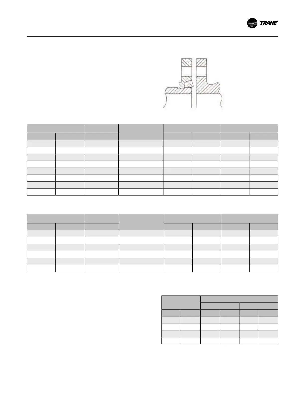
Figure 19. Typical Victaulic®® flange gasket
configuration
Table 9. Installation data for 150 psig (1034.2 kPaG) flange adapters (Style 741)
Nominal Pipe Size
Assembly
Screw Size
(a)
Number of Assembly
Screws Required
Screw Pattern Diameter
Weight
in.
mm
in. in.
mm
lb
kg
4 114.3
5/8 x 3
8 7.5 191 7.7 3.5
5 141.3
3/4 x 3-1/2
8 8.5 216 9.3 4.2
6 168.3
3/4 x 3-1/2
8 9.5 241 10.3 4.7
8 219.1
3/4 x 3-1/2
8 11.75 298 16.6 7.5
10 273.0
7/8 x 1/44
12 14.25 362 24.2 11.0
12 323.9
7/8 x 1/4
12 17 432 46.8 21.2
14 355.6
1 x 4-1/2
12 18.75 476 75 34.0
16 406.4
1 x 4-1/2
16 21.25 540 90 40.8
(a)
Screw size for conventional flange-to-flange connection. Longer screws are required when flange washer must be used.
Table 10. Installation data for 300 psig (2068.4 kPaG) flange adapters (Style 743)
Nominal Pipe Size
Assembly Screw
Size
(a)
Number of Assembly
Screws Required
Screw Pattern Diameter
Weight
in.
mm
in. in.
mm
lb
kg
4 114.3
3/4 x 3-3/4
8 7.88 200 15.3 6.9
5 141.3
3/4 x 4
8 9.25 235 17.7 8.0
6 168.3
3/4 x 4-1/2
12 10.63 270 23.4 10.6
8 219.1
3/4 x 4-3/4
12 13 330 34.3 15.6
10 273.0
1 x 5-1/4
16 15.25 387 48.3 21.9
12 323.9
1-1/8 x 5-3/4
16 17.75 451 70.5 32.0
(a)
Screw size for conventional flange-to-flange connection. Longer screws are required when flange washer must be used.
Screw-Tightening Sequence for
Water Piping Connections
This section describes a screw-tightening sequence for
flanges with flat gaskets or O-rings. Remember that
improperly tightened flanges may leak.
NNoottee:: Before tightening any of the screws, align the
flanges. Flange screw torque requirements are
provided in the following table.
Table 11. Flange screw torque recommendations for
O-ring and flat-gasket piping connections
Screw Size
Gasket Type
O-Ring
Flat
in.
mm
ft·lb N·m ft·lb N·m
3/8
9.5 25 34 12–18 16–24
1/2
13 70 95 33–50 45–68
5/8
16 150 203 70–90 95–122
3/4
19 250 339 105–155 142–210
Note: Screw size is determined by the diameter of the screw shank.
IInnssttaallllaattiioonn:: WWaatteerr PPiippiinngg