Field Wiring Procedures
RF-SVN03F-EN 13
Field Wiring Procedures
Important: Use 18 AWG, (24 pF/ft. max),
communication wire (Trane purple wire);
strip no more than 2 in. (5 cm) of the outer
conductor of shielded wire. For more
information, refer to the Unit Controller
Wiring Guide, BAS-SVN03-EN.
Connecting the Factory Wiring
Harness
1. Remove power from the entire unit to ensure that all
circuits are unpowered.
2. Connect the ReliaTel connection harnesses to J4 and
J1 as shown in Figure 9
. You may need to refer to
specific rooftop unit wiring
diagram for more details.
3. Restore power to the unit.
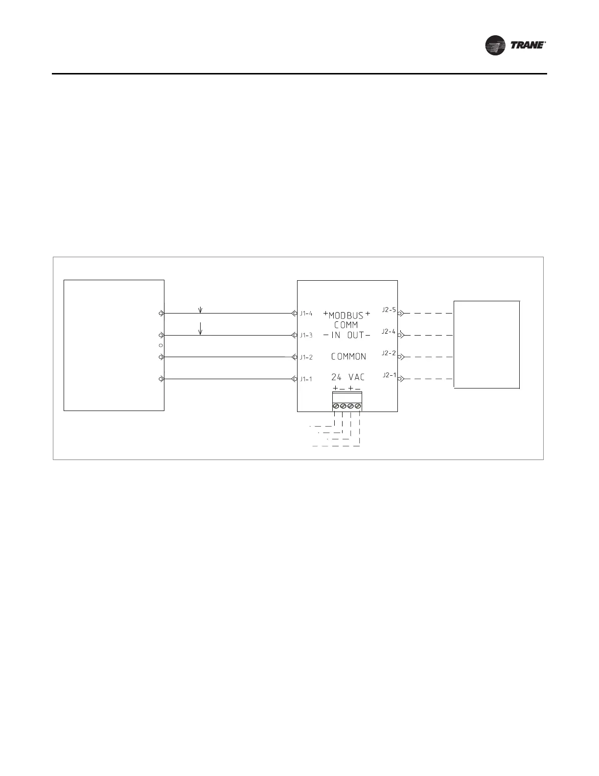
Figure 9. Generic BCI-R harness wiring diagram
Common
5-Pin Connector
4-Pin Connector
(Black)
(Black)
(Blue)
(Red)
next device in
series
(see note)
ReliaTel controller
(RTRM)
BCI-R
24 VAC
J4-1
J4-2
Empty
J4-3
MODBUS
MODBUS J4-5
J4-4
+
_
Note: Refer to the unit
schematics for
proper connection.
BACnet Wiring
1. Remove power from the entire unit to ensure that all
circuits are unpowered.
2. On the BCI-R controller, set the link select switch to
BACnet.
3. Attach the communication link wiring to the BACnet
terminal block of the
BCI-R controller.
4. Wire and tape the shields together or connect the
shields using a wire
nut as shown in Figure 10, p. 14.
5. Restore power to the unit.
Note: Do not ground the shield at the BCI-R. The entire
grounding shield must
be grounded only once per
segment. Typically, the entire shield will be
connected as one segment and grounded at the
building management controller. All four terminals
on the BCI-R terminal block will always be in use.