RT-SVX076A-EN
25
Main Electrical Power
Requirements
WARNING
Hazardous Voltage w/Capacitors!
Failure to disconnect power and discharge capacitors
before servicing could result in death or serious
injury.
Disconnect all electric power, including remote
disconnects and discharge all motor start/run
capacitors before servicing. Follow proper lockout/
tagout procedures to ensure the power cannot be
inadvertently energized. For variable frequency drives
or other energy storing components provided by
Trane or others, refer to the appropriate
manufacturer’s literature for allowable waiting periods
for discharge of capacitors. Verify with a CAT III or IV
voltmeter rated per NFPA 70E that all capacitors have
discharged.
WARNING
Proper Field Wiring and Grounding
Required!
Failure to follow code could result in death or serious
injury.
All field wiring MUST be performed by qualified
personnel. Improperly installed and grounded field
wiring poses FIRE and ELECTROCUTION hazards. To
avoid these hazards, you MUST follow requirements
for field wiring installation and grounding as
described in NEC and your local/state/national
electrical codes.
• Verify that the power supply complies with the unit
nameplate specifications.
• Inspect all control panel components; tighten any loose
connections.
• Connect properly sized and protected power supply
wiring to a field-supplied/installed disconnect switch
and to the main power terminal block (HTB1) in the unit
control panel.
• Install proper grounding wires to an earth ground.
Electric Heat Requirements
• Verify that the power supply complies with the electric
heater specifications on the unit and heater nameplate.
• Inspect the heater junction box and control panel;
tighten any loose connections.
• Check electric heat circuits for continuity.
Low Voltage Wiring
Mount the indoor thermostat, zone sensor, or
programmable zone sensor in accordance with the
corresponding thermostat installation instructions. Install
color-coded, weather-proof, multi-wire cable according to
the field wiring instructions.
Note: Refer to thermostat or zone sensor wire installation
guide for proper wire gauge.
Condensate Drain Configuration
WARNING
Hazardous Voltage!
Failure to disconnect power before servicing could
result in death or serious injury.
Disconnect all electric power, including remote
disconnects before servicing. Follow proper lockout/
tagout procedures to ensure the power can not be
inadvertently energized. Verify that no power is
present with a voltmeter.
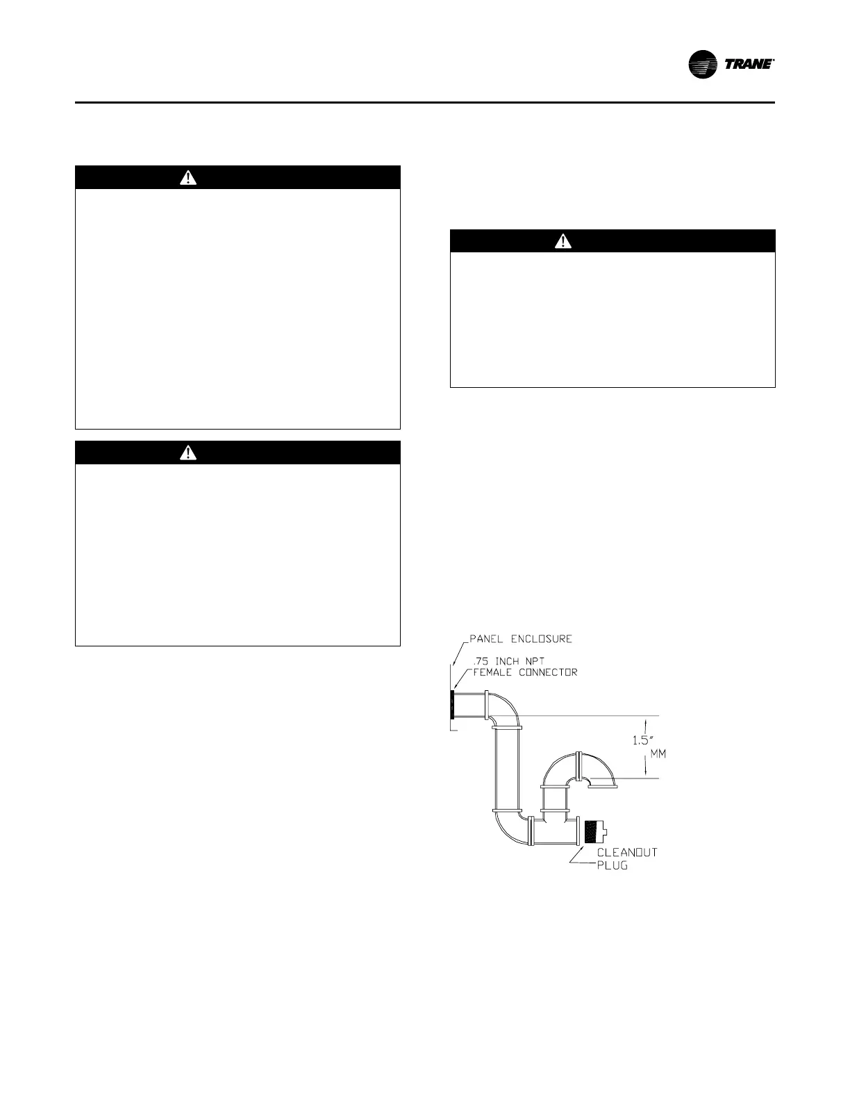
An evaporator condensate drain connection is provided on
each unit. Refer to the ductwork section in the Installation
chapter for the appropriate drain location.
A condensate trap must be installed at the unit due to the
drain connection being on the “negative pressure” side of
the fan. Install the P-Trap using the guidelines in Figure
20, p. 25.
A condensate drain line must be connected to the P-Trap.
Pitch the drain lines at least 1/2 inch for every 10 feet of
horizontal run to assure proper condensate flow. Do not
allow the horizontal run to sag causing a possible double
trap condition which could result in condensate backup due
to “air lock”.
Figure 20. Condensate trap installation
Note: Minimum if unit static is higher trap must be taller to
drain appropriately.
Filter Installation
The quantity of filters is determined by unit size. Refer to
General Data section in Packaged Rooftop Air
Conditioners Precedent™ Cooling and Electric Heat Ultra
High Efficiency 12.5 to 25 Tons — 60 Hz product catalog
Installation