26
RT-SVX076A-EN
(RT-PRC109*-EN). Access to the filters is obtained by
removing the filter access panel.
Note: Do not operate the unit without filters.
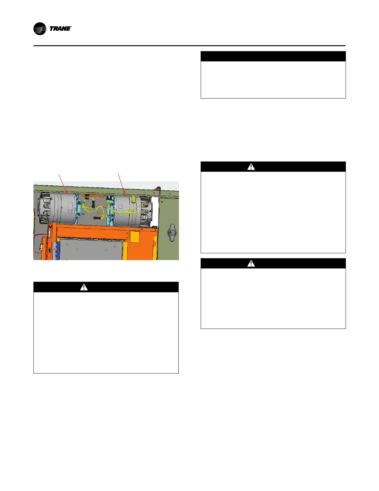
Outdoor Motor Controllers
When either an outdoor motor or an outdoor motor
controller fail, the motor and controller must be replaced
together as received in the service kit since they are a
paired tuned drive/motor assembly. Failure to do so could
result in loss of unit function. The figure below illustrates
the motor controllers are remotely mounted in the block-off
directly above the front control panel. It is not required to
replace both motor pairs.
Figure 21. Location of outdoor motor controllers
Controller 1 linked to Motor 1
(front motor closest to control panel)
Controller 2 linked to Motor 2
(rear motor)
Field Installed Power Wiring
WARNING
Proper Field Wiring and Grounding
Required!
Failure to follow code could result in death or serious
injury.
All field wiring MUST be performed by qualified
personnel. Improperly installed and grounded field
wiring poses FIRE and ELECTROCUTION hazards. To
avoid these hazards, you MUST follow requirements
for field wiring installation and grounding as
described in NEC and your local/state/national
electrical codes.
An overall dimensional layout for the field installed wiring
entrance into the unit is illustrated in the Dimensions and
Weights chapter. To insure that the unit’s supply power
wiring is properly sized and installed, follow the following
guidelines.
Verify that the power supply available is compatible with
the unit’s nameplate ratings. The available supply power
must be within 10% of the rated voltage stamped on the
nameplate. Use only copper conductors to connect the
power supply to the unit.
NOTICE
Use Copper Conductors Only!
Failure to use copper conductors could result in
equipment damage as the equipment was not
designed or qualified to accept other types of
conductors.
Important: If the unit is not equipped with an optional
factory installed non-fused disconnect switch
or circuit breaker, a field supplied disconnect
switch must be installed at or near the unit in
accordance with the National Electrical Code
(NEC latest edition).
Main Unit Power
WARNING
Proper Field Wiring and Grounding
Required!
Failure to follow code could result in death or serious
injury.
All field wiring MUST be performed by qualified
personnel. Improperly installed and grounded field
wiring poses FIRE and ELECTROCUTION hazards. To
avoid these hazards, you MUST follow requirements
for field wiring installation and grounding as
described in NEC and your local/state/national
electrical codes.
WARNING
Hazardous Voltage!
Failure to disconnect power before servicing could
result in death or serious injury.
Disconnect all electric power, including remote
disconnects before servicing. Follow proper lockout/
tagout procedures to ensure the power can not be
inadvertently energized. Verify that no power is
present with a voltmeter.
Standard Wiring
1. Location of the applicable electrical service entrance is
illustrated in the Dimensions and Weights chapter.
Complete the unit’s power wiring connections at HTB1
main power terminal block in unit control panel. Refer to
the customer connection diagram that is shipped with
the unit for specific termination points.
2. Provide proper grounding for the unit in accordance
with local and national codes.
Optional TBUE Wiring (Through-the-
Base Electrical Option)
Location of the applicable electrical service is illustrated
below. Refer to the customer connection diagram that is
shipped with the unit for specific termination points. The
termination points, depending on the customer option
Installation