About Trane and American Standard Heating and
Air Conditioning
Trane and American Standard create comfortable, energy
efficient indoor environments for residential applications.
For more information, please visit www.trane.com or
www.americanstandardair.com
The AHRI Certified mark indicates company participation in the
AHRI Certification program. For verification of individual certified
products, go to ahridirectory.org.
The manufacturer has a policy of continuous data improvement and it
reserves the right to change design and specifications without notice. We
are committed to using environmentally conscious print practices.
© 2020
18-BG04D1-12A-EN 29 May 2020
Supersedes 18-BG04D1-12-EN (June 2019)
Table 7. IGN LED Diagnostic Indicators
Status LEDs
IGN Board Diagnostic Codes
There are two LEDs on the IGN board that provide status and
diagnostic information. Refer to Table 7 for a description of the
LED codes.
SteadyOFF CheckPowerorFailedBoard 2Flashes
SystemLockout:Failedtodetector
sustain flame
SlowFlashRate Normal,NoCallforHeat 3Flashes
Pressureswitchproblemdetected
FastFlashRate Notused 4Flashes
HighLimitswitchprotectiondevice
open
SteadyON Normal,NoCallforHeat 5Flashes
Flamesensedandgasvalvenot
energizedorflamesensedandno"W"
signal
6Flashes
FlameRolloutSwitchopen
7Flashes
Thermostatmiswired;W1&W2
Fast Flash Rate:TheLEDwillflashonfor1/4second,andofffor1/4second
Slow Flash Rate:TheLEDwillflashonfor3/4second,thenofffor1/4second.
Thepausebetweengroupsoffastflashesis3seconds.
Status LED Liteport LED
IGN Diagnostic Indicators Flash Codes
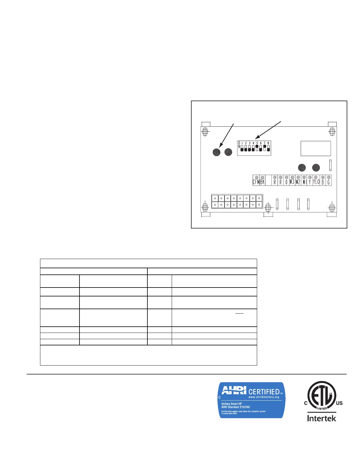
Figure 23. ECM Fan Control
ECM Fan Motor Adjustments
If the airflow needs to be increased or decreased, see the
Airflow Table in the SERVICE FACTS. Information on chang-
ing the speed of the blower motor is in the Blower Performance
Table. Blower speed changes are made on the ECM Fan Control
mounted in the control box. The ECM Fan Control controls the
variable speed motor. There is a bank of 8 dip switches, (See
Figure 23 below), located on the board. The dip switches work in
pairs to match the cooling/heat airflow (CFM/TON), Fan off-delay
options and electric heat airflow adjustment. The switches appear
as shown in the Figure below.
6. Remove the manifold retaining screws and pull the burner-
manifold assembly from the heat exchanger.
7. Remove the inlet turbulators being careful not to break or dam-
age them.
8. Wipe the flue box and flue baffles clean with a clean, dry cloth.
9. Never use combustible cleaning fluids on any part of the furnace.
10. Replace all gaskets with new ones.
11. Replace all damaged or broken turbulators with new ones.
12. Reassemble the unit by reversing Steps 2 through 7 above.
Take care that all gaskets seat properly.
13. Check all wires for correct installation by referring to the unit’s
electrical wiring diagram in the SERVICE FACTS.
14. Leak test all gas line connections with a soap and water solution
or the equivalent.
15. Re-install the CONTROL/HEAT access panels and the flue
hood.
16. Visually inspect the unit to ensure that the airflow opening for
combustion is not obstructed.
17. Follow the start-up procedure on page 21 to place the unit back
in service.
CFM
SELECTION
LIGHT
DIP
SWITCHES
CFM FAN
RW3 W2 W1
Y
Y LO
J
21C800796P01
CNT03600