18
18-EB30D1-1G-EN
Table 6. Filter Sizes (field supplied filter rack)
81,7
120,1$/
&)0
),/7(5
D
6,=(
6T )W
),/7(5
5(6,67$1&(
³:&
a&&$
a&&$
a&&$
a&&$
a&&$
a&&$
D
I)LOWHUV PXVW EH LQVWDOOHG LQ WKH UHWXUQ DLU V\VWHP 7KH DERYH VTXDUH
IRRWDJHV DUH EDVHG RQ )30 IDFH YHORFLW\ ,I SHUPDQHQW ILOWHUV
DUH XVHG VL]H SHU PIJ 5HFRPPHQGDWLRQ ZLWK FOHDU UHVLVWDQFH RI
´:&
II mmppoorrttaanntt:: Air filters and media wheels or plates shall
meet the test requirements in UL 900
EElleeccttrriiccaall WWiirriinngg
NNoottee:: This unit is factory wired for 230V. See wiring
diagram for 208V conversion.
EElleeccttrriiccaall CCoonnnneeccttiioonnss
Electrical wiring and grounding must be installed in
accordance with local codes or, in the absence of local
codes, with the National Electrical Code ANSI/NFPA 70,
Latest Revision.
EElleeccttrriiccaall PPoowweerr
It is important that proper electrical power be available
for the unit. Voltage variation should remain within the
limits stamped on the unit nameplate.
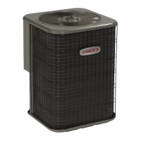
DDiissccoonnnneeccttSSwwiittcchh
Provide an approved weatherproof disconnect within
close proximity and wwiitthhiinnssiigghhttoofftthheeuunniitt..If
disconnect must be mounted to the cabinet, the
location shown in
Table 9, p. 18 should be the only one
considered.
OOvveerrCCuurrrreennttPPrrootteeccttiioonn
The branch circuit feeding the unit must be protected
as shown on the unit's rating plate.
PPoowweerrWWiirriinngg
The power supply lines must be run in weather-tight
conduit to the disconnect and into the side of the unit
control box. Provide strain relief for all conduit with
suitable connectors.
Provide flexible conduit supports whenever vibration
transmission may cause a noise problem within the
building structure.
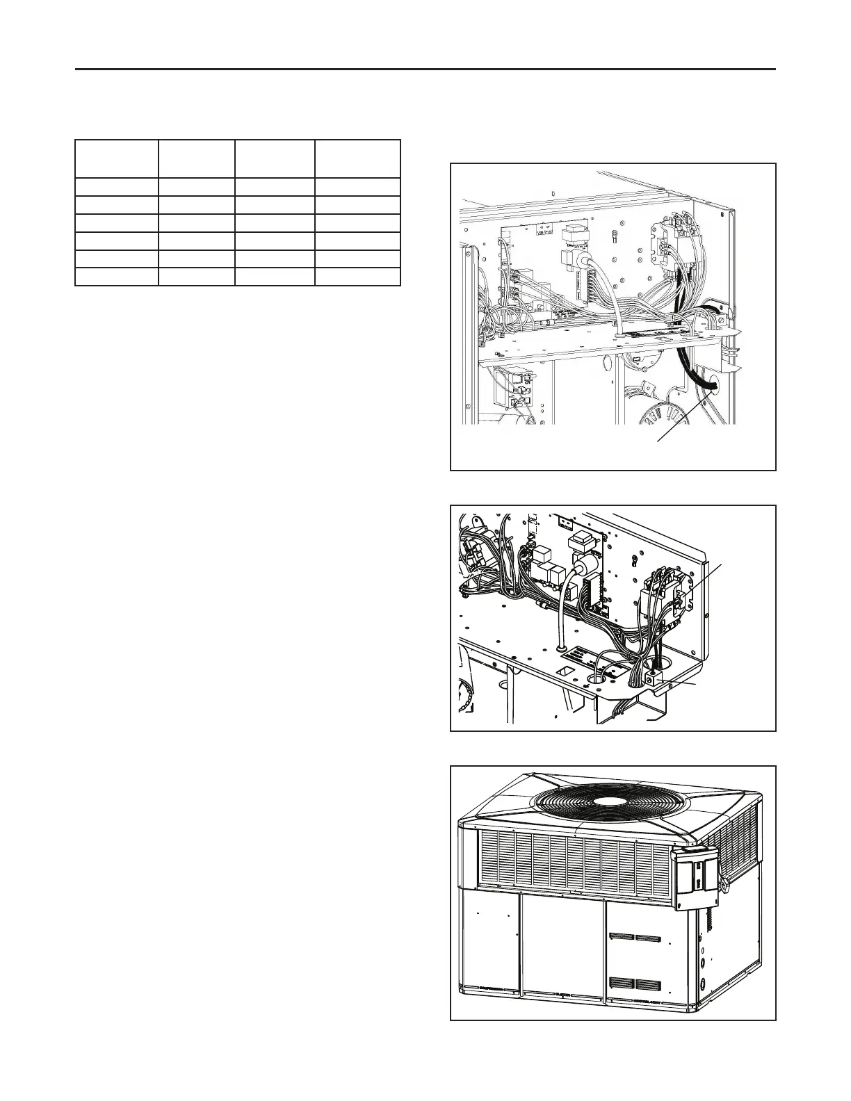
1. Remove the Control/Heat access panel. Pass the
power wires through the Power Entry hole in the
end of the unit. See Table 7, p. 18.
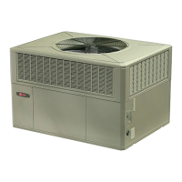
2. Connect the high voltage wires to the appropriate
contactor terminals. Single phase units use a two
(2) pole contactor and three phase units use three
(3) pole contactor. Connect the ground to the
ground lug on the chassis. See Table 9, p. 18.
Ensure all connections are tight.
Table 7. Power Wiring
Run power supply lines through weather-tight
conduit and secure to unit with strain relief.
Table 8. Power Connections
Unit Ground
Lug
Contacto
Table 9. Mounted Disconnect Location
SStteepp44——UUnniittIInnssttaallllaattiioonn