14 18-BC96D1-1A-EN
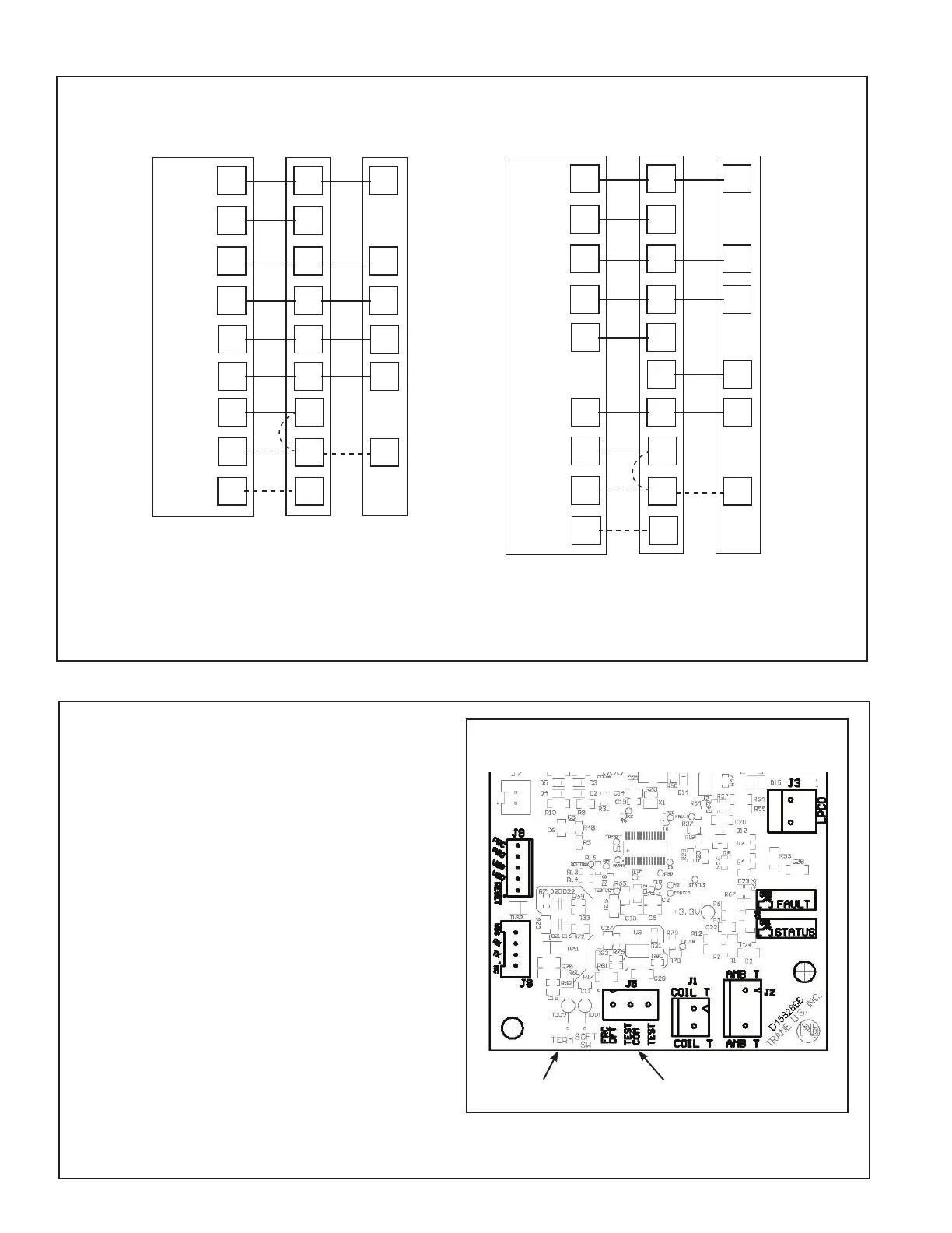
11.2 Low Voltage Hook-up Diagrams
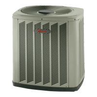
Defrost controls have a selectable termination tem-
perature. As shipped, defrost will terminate at 47°F.
For a higher termination temperature, cut Jumper
J2 to achieve 70°F. See Service Facts shipped in
the outdoor unit for more information.
Pin Identification on J5 (See Illustration)
1. TEST_COMMON (Shorting to FRC_DFT
causes the control to initiate Forced Defrost.
Leaving this pin open results in the normal
mode of operation.)
2. FRC_DFT = Forced Defrost (Short TEST_
COMMON to this pin for two (2) seconds to
initiate a forced defrost. Remove the short
after defrost initiates.)
Defrost Control Checkout
Normal operation requires:
• Status LED on board flashing 1 time/second
in standby or 2 times/second with a call for
heating or cooling.
• 24V AC between R & B
• 24V AC between Y, Y0 & B with unit operating
• Defrost initiation when FRC_DFT pin is shorted to TEST_COMMON pin.
If a defrost control problem is suspected, refer to the service information in control box.
Defrost Board Detail
Jumper J2 J5 Test Pins
11.3 Defrost Control
Thermostat Air Handler
Outdoor
Unit
R
G
B
W1
W2
R
B
O
X2
R
G
B/C
B/C
O
Y1
W
Blue
24 VAC HOT
FAN
24 VAC
Common
SOV
COOL/HEAT
1st STAGE
HEATING
2nd STAGE
EMERGENCY
HEAT
Pink Black
White
X2
O
Y1
Y2
Y1
Y2
COOL/HEAT
2nd STAGE
Y2
Thermostat Air Handler
Outdoor
Unit
R
G
B
W1
W2
R
B
O
Y
O
Y
O
X2
R
G
O
Y
l
W
Blue
O
Y2
Y
l
24 VAC HOT
FAN
24 VAC
Common
SOV
COOL/HEAT
1st STAGE
Y2
Y2
COOL/HEAT
2nd STAGE
HEATING
2nd STAGE
EMERGENCY
HEAT
Pink Black
White
X2
•
Units with pigtails require wirenuts for connections.
•
In systems with multiple stages of electric heat, jumper W1 and W2 together if comfort control has only one stage of heat.
** TEM6 only - When using a BK enabled comfort control, cut BK jumper and bypass Y1 and Y2 at the air handler. Connect BK from
comfort control to BK of the air handler
•
TAM7 only - When using a BK enabled comfort control, cut BK jumper on the AFC and connect BK from comfort control to BK of
the air handler.
T
AM7 DIP switches must be configured for “HP: 2-Stage/1 Compressor”.
BK
WH/BLK
BK
WH/BLK
BK
WH/BLK
BK
WH/BLK