14
18-GF79D1-1A-EN
NNoottee:: Remove nitrogen pressure and repair any
leaks before continuing.
VVaaccuuuumm tteesstt::
IImmppoorrttaanntt:: Do not open the service valves until the
refrigerant lines and indoor coil leak
check and evacuation are complete.
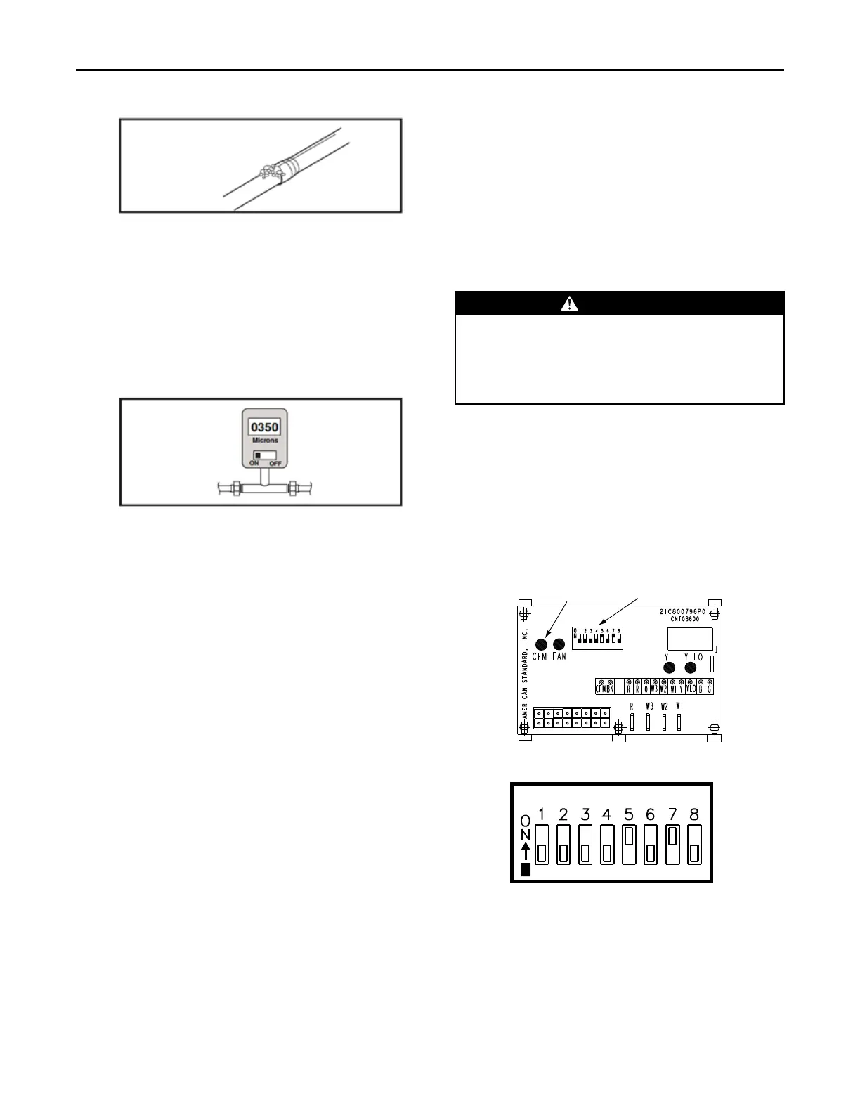
• Evacuate until the micron gauge reads no
higher than 350 microns, then close off the
valve to the vacuum pump.
• Observe the micron gauge. Evacuation is
complete if the micron gauge does not rise
above 500 microns in one (1) minute and 1500
microns in ten (10) minutes.
• Once evacuation is complete, blank off the
vacuum pump and micron gauge, and close the
valve on the manifold gauge set.
All procedures for charging the system with
refrigerant shall be according to the instructions
provided by the manufacturer of the outdoor unit.
IImmppoorrttaanntt:: Under no circumstances shall potential
sources of ignition be used in the
searching for or detection of refrigerant
leaks.
After charging the system, all indoor field-made
joints of the field piping shall be checked for
refrigerant leaks using an electronic leak detector
calibrated for R-454B having a sensitivity of 5 grams
per year or better.
6. MMeetteerriinngg DDeevviiccee
All units are shipped and installed with an
internally-checked, non-bleed TXV designed for air
conditioning or heat pump operation. Some
outdoor models may require a start assist kit. See
outdoor unit for more information.
7. BBlloowweerr
This unit is supplied with a variable speed motor
with a direct drive blower wheel which can obtain
various air flows. The unit is shipped with factory
set cooling and heating air flows. Performance
tables are available for additional airflow settings.
Disconnect all power to the unit before making any
adjustments to the airflow settings. Be sure to
check the air flow and the temperature drop across
the evaporator coil to ensure sufficient air flow.
NNoottee:: For optimal performance, seal the seams of
the front panels using an appropriate tape to
reduce air leakage.
8. AAiirrffllooww AAddjjuussttmmeenntt
CCAAUUTTIIOONN
EEQQUUIIPPMMEENNTT DDAAMMAAGGEE!!
FFaaiilluurree ttoo ffoollllooww tthhiiss pprroocceedduurree mmaayy rreessuulltt iinn
eeqquuiippmmeenntt ddaammaaggee..
DDiissccoonnnneecctt ppoowweerr ttoo tthhee aaiirr hhaannddlleerr bbeeffoorree
cchhaannggiinngg ddiipp sswwiittcchh ppoossiittiioonnss..
Blower speed changes are made on the ECM Fan
Control. The ECM Fan Control controls the variable
speed motor.
There is a bank of 8 dip switches. The dip switches
work in pairs to match the airflow for the outdoor
unit size (tons). cooling airflow adjustment, Fan off-
delay options, and heating airflow adjustment. The
switches appear as shown in Figure 3, p. 14.
Figure 2. ECM Fan Control
CFM
SELECTION
LIGHT
DIP
SWITCHES
Figure 3. Dip Switches
DIP SWITCHES (TYPICAL SETTINGS)
COOLING
HEATING
AIRFLOW
FAN OFF
DELAY
AUXILARY
HEAT SPEEDS
If the airflow needs to be increased or decreased,
see the Airflow Label on the air handler or Blower
Performance Table.
IInnssttaallllaattiioonn IInnssttrruuccttiioonnss
 Loading...