18-AC128D1-1B-EN 15
STEP 9 - Record System Information for
reference.
Record system pressures and temperatures
after charging is complete.
Outdoor model number = _________________
Measured Outdoor Ambient = __________ º F
Measured Indoor Ambient = __________ º F
Measured Liquid Line Temp = __________ º F
Measured Suction Line Temp = __________ º F
Liquid Gage Pressure = __________ PSI
Suction Gage Pressure = __________ PSI
STEP 10 - If repairs must be made after system is charged, properly and safely remove and isolate refrigerant and
purge the section of the system needing repair with oxygen free nitrogen prior to opening the circuit.
The refrigerant charge should be recovered into the correctly marked recovery cylinders. Ensure that the correct
number of cylinders for holding the total system charge is available. Only use cylinders designated for the recovered
refrigerant and labelled for that refrigerant. Cylinders shall be complete with pressure-relief valve and associated
shut-off valves in good working order.
Ensure that the outlet for the vacuum pump is not close to any potential ignition sources and that ventilation is
available.
The recovered refrigerant shall be returned to the refrigerant supplier in the correct recovery cylinder. Do not mix
refrigerants.
If compressors or compressor oils are to be removed, ensure that they have been evacuated to an acceptable level
to make certain that FLAMMABLE REFRIGERANT does not remain within the lubricant.
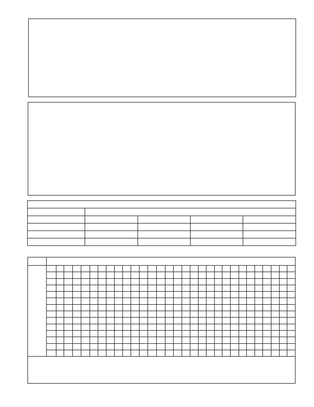
Indoor Wet Bulb Temp (F)
Outdoor
Dry
Bulb
Temp.
(F)
50 51 52 53 54 55 56 57 58 59 60 61 62 63 64 65 66 67 68 69 70 71 72 73 74 75 76 77 78
55 7 9 10 11 12 14 15 17 18 20 21 23 24 26 27 29 30
60 5 7 8 9 10 12 13 15 16 18 19 21 22 24 25 27 28 30 31
65 4 6 8 101113141617 18 19 2122242527282731
70 5 7 8 101113 14 16 1718192122242527283031
75 5 6 7 9 10 12 14 16 18 19 21 22 24 26 28 29 31 32
80 4 6 7 9 10 11 12 14 16 18 19 21 23 25 26 28 29 31 33
85 4 6 7 9 10 13 14 16 18 20 21 23 24 26 28 29 30 31 32
90 4 6 8 1011131416182022242527283031
95 4 6 8 1013141618202223 25 262829
100 6 8 10 12 13 16 18 20 21 23 25 27 29
105 4679111315182022242628
110 4 7 9 11 13 16 18 21 23 26 28
115 6 9 12 14 16 19 21 24 26
Using a digital psychrometer, measure the return air wet-bulb temperature at the unit just before the coil. Also measure the outdoor dry-bulb tem-
perature. Use these temperatures to locate the target superheat on the charging table. Do not attempt to charge the system if these conditions fall
outside of this charging table.
ADD refrigerant to DECREASE total superheat. REMOVE refrigerant to INCREASE total superheat. Always allow 10 to 15 minutes of operature
after any refrigerant or air flow change prior to determining the final superheat.
Fixed Orifice Superheat Charging Table
Nitrogen Purge Times
Flow Rate Lineset Length
CuFT/Hr < 50 feet < 100 feet < 150 feet < 200 feet
15 2 Minutes 4 Minutes 6 Minutes 8 Minutes
30 1 Minute 2 Minutes 3 Minutes 4 Minutes
60 1 Minute 1 Minute 2 Minutes 2 Minutes