18-BC117D1-1B-EN 11
Mitigation Board Guidelines
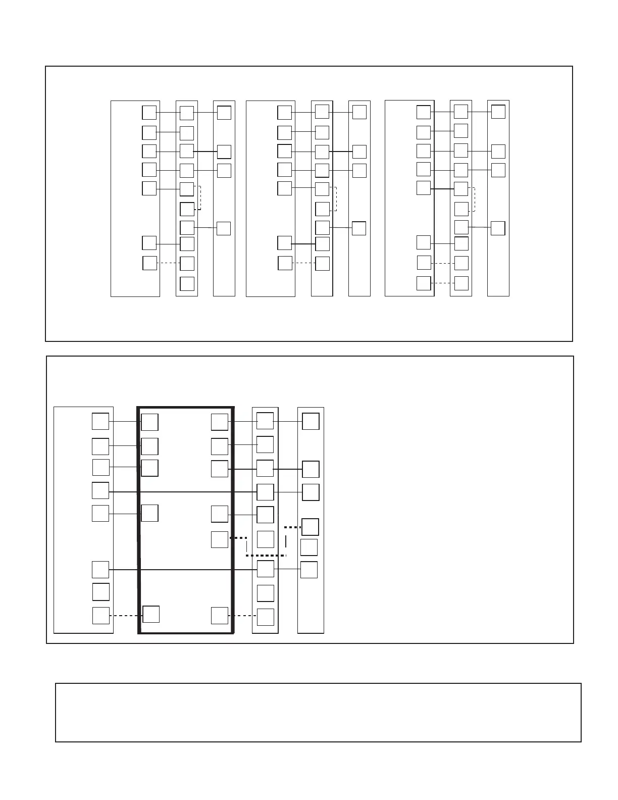
11.2 Low Voltage Hook-up Diagrams
With 5TEM6
Thermostat Air Handler
Outdoor
Unit
R
G
B
W1
W2
R
B
O
Y
R
G
B/C
O
Y
W1
Blue
24 VAC HOT
FAN
24 VAC
Common
COOL/HEAT
1st STAGE
HEATING
1st STAGE
Pink
White
W2
O
Y1
.
Y2
Yo
5)
BK
WH/BLK
1) Units with pigtails require wirenuts for connections.
2) Cap all unused wires.
3) When BK is used, do not connect Y2 at the air handler.
4) When BK is used, cut the jumper between R and BK on the
control board. See indoor wiring schematic for details.
5) In AC systems, for multiple stages of electric heat, jumper
W1 and W2 together if comfort control has only one stage of heat.
With 5TEM4
ThermostatAir Handler
Outdoor
Unit
R
G
B
W1
W2
R
B
O
Y
R
G
B/C
O
Y
W1
Blue
24 VAC HOT
FAN
24 VAC
Common
COOL/HEAT
1st STAGE
HEATING
1st STAGE
Pink
White
W2
O
Y1
Y2
Yo
3)
1) Units with pigtails require wirenuts for connections.
2) Cap all unused wires.
3) In AC systems, for multiple stages of electric heat, jumper W1
and W2 together if comfort control has only one stage of heat.
With 5TAM5
ThermostatAir Handler
Outdoor
Unit
R
G
B
W1
W2
R
B
O
Y
R
G
B/C
O
Y
W1
Blue
24 VAC HOT
FAN
24 VAC
Common
COOL/HEAT
1st STAGE
HEATING
1st STAGE
Pink
White
W2
O
Y1
Y2
Yo
3)
W3
Brown
1) Units with pigtails require wirenuts for connections.
2) Cap all unused wires.
3) In AC systems, for multiple stages of electric heat, jumper
W1 and W2 together if comfort control has only one stage of heat.
W3
Brown
HEATING
2nd STAGE
HEATING
2nd STAGE
HEATING
2nd STAGE
HEATING
3rd STAGE
3)
• The approved ID/OD combination will provide sufficient safe ventilation in case of a leak.
• Refer to Indoor Unit Installer’s Guide for correct specifications on indoor unit install.
• All systems require mitigation boards so an altitude adjustment factor may be required.
• Mitigation Control Board needs to be included in an A2L System.
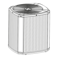
Evaporator Coil MCBFurnance
Outdoor
Unit
R
G
B
W1
W2
R
B
O
Y/Y1
R
G
B
Yi
O
Y1
Y2
BK
Yo
3)
3)
BKi
Y2
3)
X2
R
G
B
Y1
BK
R
G
B/C
O
Y1
W1
24 VAC HOT
FAN
24 VAC
Common
COOL
HEATING
W2
BK
Thermostat
3)
1) Units with pigtails require wirenuts for
connections. Cap all unused wires.
2) For 24V control, connect factory supplied
harness to circuit board at evaporator.
Complete all other wiring connections at the furnace.
3) For 2 stage systems, connect W2 to W2 and Y2 to Y2.