BAS-SVX40K-EN
51
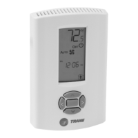
Figure 38. Relative humidity sensor module installation
Install the RH sensor
module in this
location on a WCS
A WCS with an RH sensor module installed on it displays the RH humidity measurement when you
scroll through the display sequence.
Note: If using a WCS-SB/R with a humidity sensor module, take note that the humidity reading will come
from the location of the mounted sensor, not the external probe location.
Replacing the Sensor Cover
To replace the cover, hook the cover over the top of the back plate. Apply light pressure to the bottom of
the cover until it snaps in place.
WCS-SO, -SCO
2
, -SB/R Error Codes
Each error code is described in the following table.
Possible Cause Explanation/Resolution
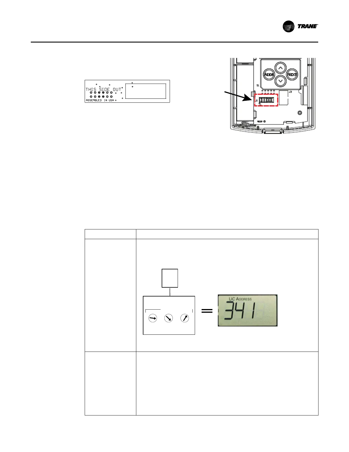
Sensor is not associated
with UC (E1)
• Verify that the unit controller and WCI firmware are up to date.
• The configured address in the sensor does not match the dials of a UC for any WCI in the same
wireless network. Re-associate the sensor with the WCI by correcting the UC address in the
sensor.
1
2
2
3
4
5
6
7
8
9
0
1
3
4
5
6
7
1
2
3
4
5
6
7
8
9
0
8
9
0
UC
WCS
Match to UC
ADDRESS
WCI
Refer to “WCS-SO, -SCO
2
, -SB/R Network Joining and Controller Association,” p. 44 for information
about E1 and E2 errors.
Sensor has not joined the
network. (E2)
• Verify that the network is open.
• Normal for sensor configured with GRP-NET 0-0.
• Verify that the sensor has the correct group (GRP) and network (NET) addresses.
• Verify that the sensor is within radio range.
• If the sensor has previously joined the network, verify that WCIs in range are powered up. From
the balnk screen or error screen, press the UP arrow to force manual association. Otherwise,
set the correct GRP and NET addresses and open the wireless network to allow the sensor to
join.
Refer to “WCS-SO, -SCO
2
, -SB/R Network Joining and Controller Association,” p. 44 for information
about E1 and E2 errors.
WCS–SO/SCO
2
and –SB/R Installation
 Loading...


