31
STEP 5 - Secure the sheathed wiring to the control
pocket mounting plate using the factory supplied zip
ties attached to the tabs to as shown.
STEP 6 - Refrigerant Switch
Set the system refrigerant to either R-410A or R-22
using the Refrigerant Switch located on the Expansion
Valve Control board (EVC) in the Control Pocket.
Factory default is R-410A.
Note: The power must be shut off and then re-
applied in order for the EVC to recognize the
change.
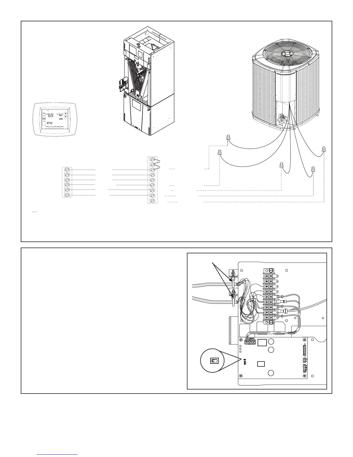
Air Handler Hook-up Diagram
Heat Pump
Comfort Control
Air Handler
Field wiring
Yellow
Blue
Black
(X2)
Red
Orange
Heat Pump
Red
Yellow
Orange
Green
White
Blue
Yellow
Green
White
Blue
B
B - Blue
W
G
Y
Y - Yellow
R
Red
O
Orange
O **
R **
B
YI
W1
YO
G
W2
W3 *
R - Red
O - Orange
W1 - White
SW1
410
22
1
2
3
SW1
410
22
1
2
3
SW1
410
22
• * For multiple stages of electric heat, jumper W1, W2, and W3 together if comfort control has only one stage of heat
• ** R to O jumper must be removed for heat pump system.
• YI and YO connections must be made as shown for freeze protection and internally mounted condensate overflow circuits to work
properly
• Internally mounted condensate switch is optional and must be ordered separately
• If a 3rd party condensate overflow switch is installed, it should be wired between Y of the thermostat and YI of the EEV control.
Wire Ties
 Loading...