16 BAS-SVP09B-EN
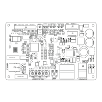
LEDs and Switches
Table 1. Interpreting the LEDs and switches
LED type LED activity Indicates...
Service LED
Solid green
The controller is in boot mode. The controller will be placed
into boot mode if the service pin is held in when power is
applied. In boot mode, the controller is non-operational and
is waiting for a new main application to be downloaded.
While in boot mode, the system will not run any
applications.
Not illuminated Application code is running; operating normally
Status LED
Solid green Normal operation
Blinking green The controller is updating the flash
Solid red The controller has malfunctioned
Blinking red Alarms or point faults are present
Not illuminated The controller is off
Link Tx/Rx
TX blinks green Data is being transferred, received, or transmitted
RX blinks yellow
Blinks at the data transfer rate when the unit receives data
from other devices on the link
• ON solid yellow; indicates there is reverse polarity
Not illuminated No activity is occurring
Modbus Tx/Rx
Blinking Data is being transferred, received, or transmitted
Not illuminated No activity is occurring
Link LEDs
BACnet is illuminated The Link Switch has been set to wired communication
IMC is illuminated The Link Switch has been set to wireless communication
Switch/Button type Purpose
Link Select Switch Use this switch to select wired communication (BACnet) or wireless communication (IMC)
Service Button Press this button and restart the controller to run the boot code
Rotary Switches Use these switches to set unique MS/TP MAC addresses

 Loading...