BAS-SVP09B-EN 5
Getting Started
This section describes the necessary software, tools, and initial tasks that are required for a
successful integration.
Required Software and Tools
The following are required:
• Tracer™ BACnet Setup Tool OR Tr
acer™ TU Service Tool, version 6.0 or higher
• A USB cable (for use with Tracer TU)
• A 1/8 inch (3 mm) flat-bladed screwdriver
What to Do First
It is best practice to perform the following tasks in the order in which they are listed:
• Set device addresses on the BCI-R rotary switch
es (see following section).
• Select either wired or wireless communication using the link select switch on the BCI-R (p. 6).
• Configure the BCI-R by using e
i
ther the Tracer BACnet Setup Tool (BST) or Tracer TU (p. 7).
– The default baud rate is 76,800 bps.
– The default software device ID
is the MAC address.
– The device units do not have defaults; the BST or Tracer TU will display the device units of
the controller to whic
h it is connected.
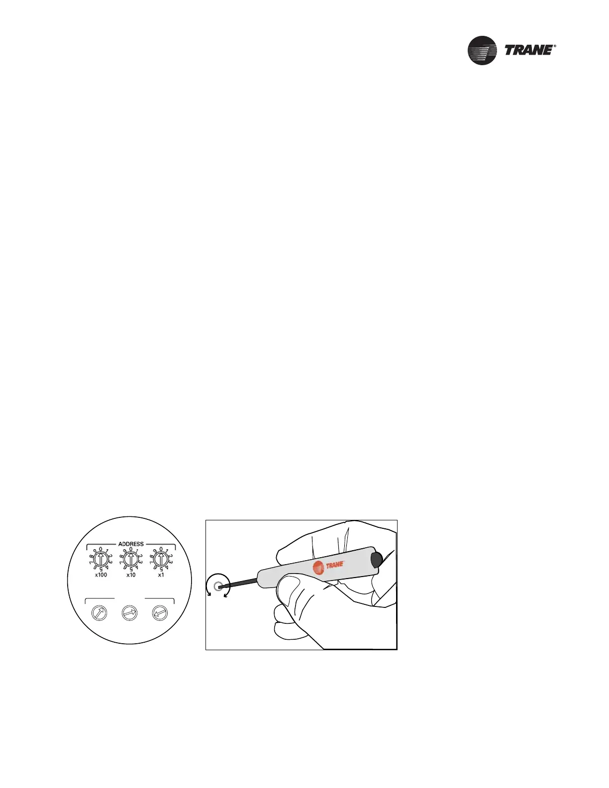
Setting Addresses on the Rotary Switches
There are three rotary switches on the front of the BCI-R controller that are used to define a three-
digit address when the BCI-R is installed on a BACnet communications network. The three-digit
address setting is the BACnet MAC address. Figure 1 shows how to set addresses.
For more information about rotary switches, see “Understanding the MAC Address and BACnet
Device ID,” p. 9.
Note: All devices
are MS/TP masters with valid MAC addresses of 001 to 127 for BACnet.
Figure 1. Setting addresses on the rotary switches
0
5
1
3
6
2
9
4
8
7
ADDRESS
0
1
2
3
4
5
6
7
8
9
x1
0
1
2
3
4
5
6
7
8
9
x10
0
1
2
3
4
5
6
7
8
9
x100
Setting addresses to 127
(before and after)
Use a 1/8 in (3mm)flat-bladed
screwdriver to set rotary
switches.
Important: Each device on the BACnet MSTP link must have a unique rotary
switch setting, otherwise, communication problems will occur.
Before
After

 Loading...