Page 25
(**) A Victaulic kit must be provided for every side of the unit (user and or source one) to be connected.
In case of selection of external hydraulic kit, it is necessary to provide 1 kit for the unit and 1 kit for the external hydraulic kit
module.
E.g. : CGWF +external water kit module + water tank module + Victaulic kit on user side
Select nr. 3 victaulic kits (1 kit for unit + 1 kit for pump hydraulic kit + 1 kit for water tank)
7.5.1
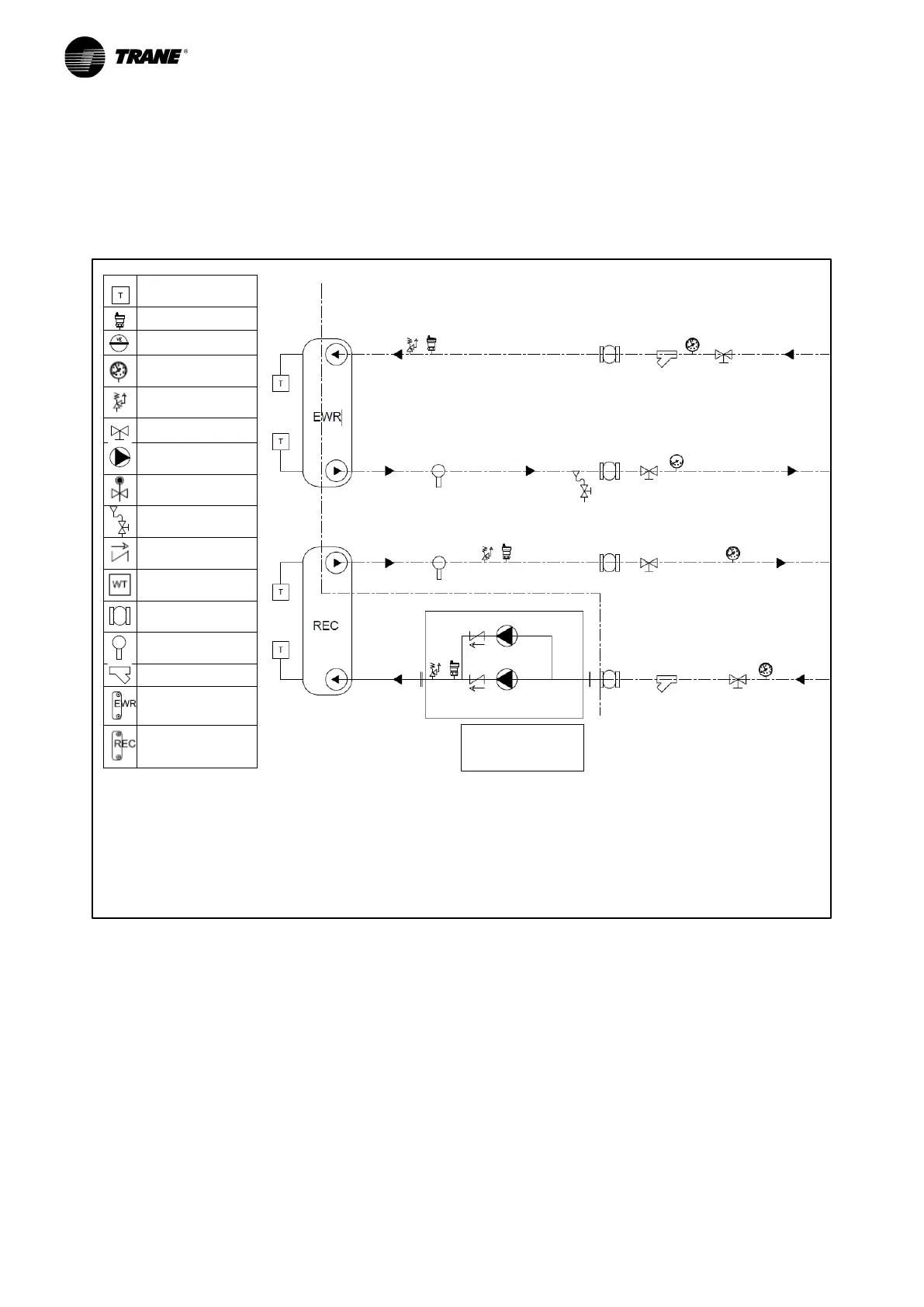
Hydraulic diagram for CGWF (SE and HE) - CXWF units and hydraulic modules with no pump no tank on
user side, and 2 pumps without tank on source side.
Temperature
Probe drafted
Relief Valve
Expansion Vessel
Gauges
Shut Off Valve
Pump
Water Charge
Water Discharge
Check Valve
Water Tank
Flexible joint
Flow Switch
Filter
User Heat
Exchanger
Source Heat
Exchanger
Remote Connections
at customer care
Plant side
REMARKS:
1
apply the flow switch in a straight pipe far from filters, valves, etc. with length at least 5 times the
diameter of pipe upstream and downstream the unit
2: the connection of the unit to the hydraulic modules is at customer care