Page 29
7.5.5
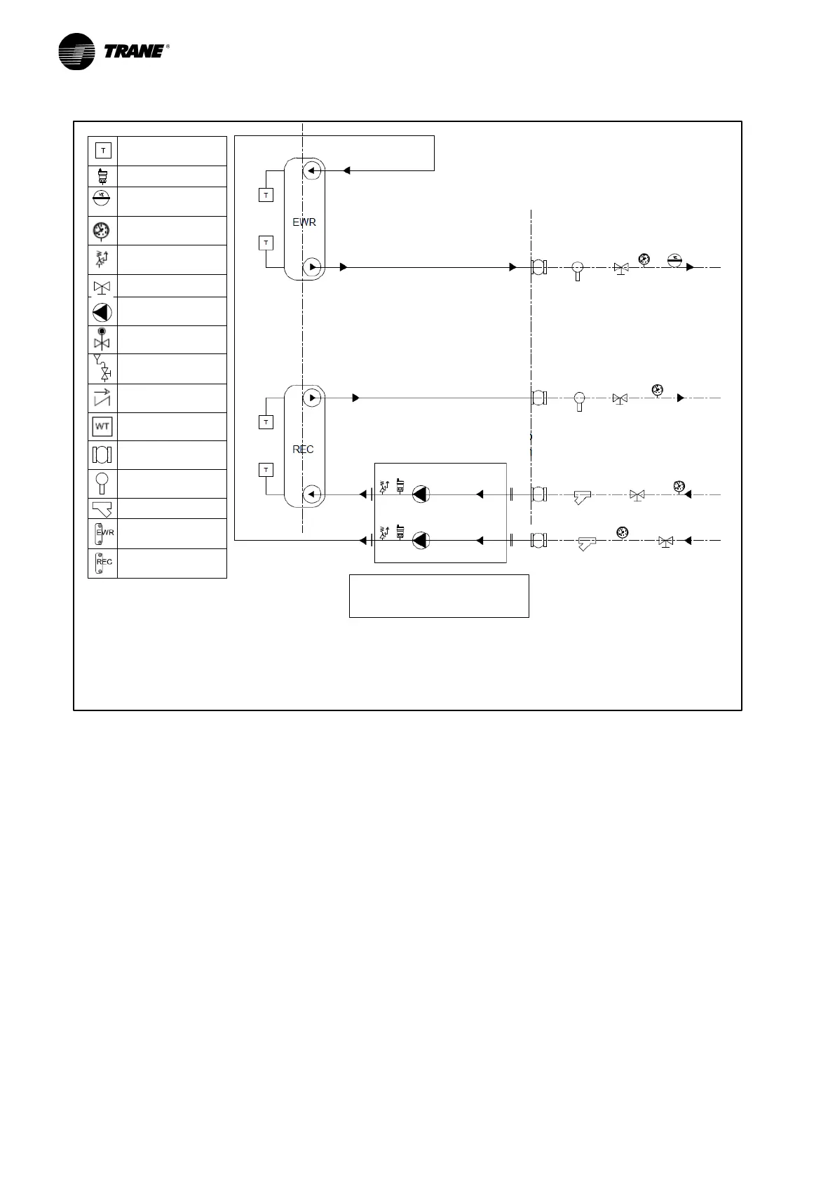
Hydraulic diagram for CGWF (SE and HE) - CXWF units and hydraulic modules with 1 pump without
tank on user side and 1 pump on source side.
Temperature
Probe drafted
Relief Valve
Gauges
Shut Off Valve
Pump
Water Charge
Check Valve
Water Tank
Flexible joint
Flow Switch
Filter
Plant side
customer care
1 pump user side + 1 pump
source side kit
REMARKS:
1
apply the flow switch in a straight pipe far from filters, valves, etc. with length at least 5 times the
diameter of pipe upstream and downstream the unit
2: the connection of the unit to the hydraulic modules is at customer care