RT-SVX50M-EN
21
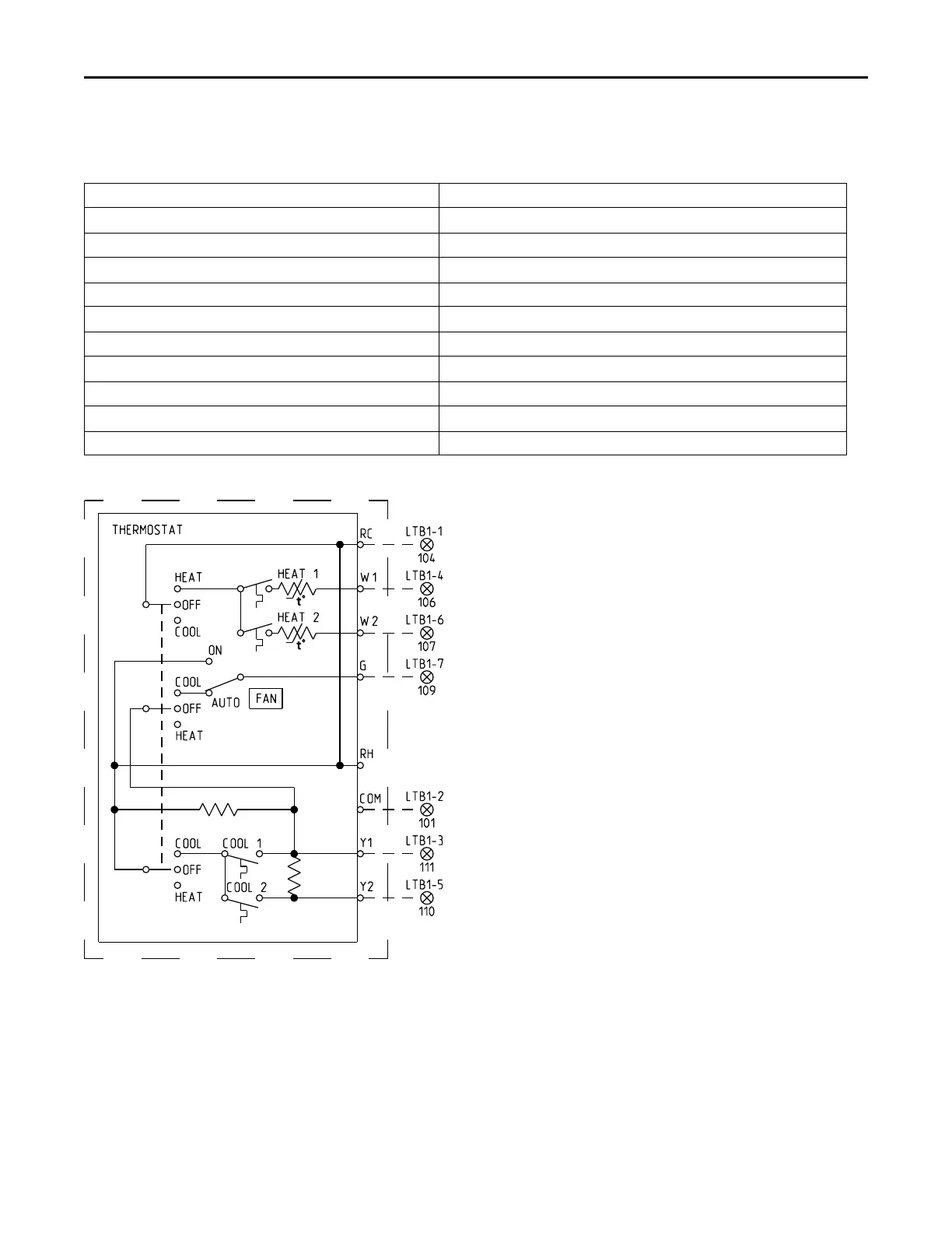
conduit with the high voltage power wiring. 5. Route low voltage wiring as per Figure 14, p. 21.
Table 3. Electromechanical thermostat 24V AC conductors with electromechanical unit
Distance from Unit to Control Recommended Wire Size
0 - 30 feet
22 gauge
0 - 9.1 m 0.33 mm^2
31 - 50 feet
20 gauge
9.5 - 15.2 m 0.50 mm^2
51 - 75 feet
18 gauge
15.5 - 22.9 m 0.75 mm^2
76 - 125 feet
16 gauge
23.1 - 38.1 m 1.3 mm^2
126 - 200 feet
14 gauge
38.4 - 60.9 m 2.0 mm^2
Figure 14. Conventional thermostat field wiring diagram
Voltage Imbalance
Three phase electrical power to the unit must meet
stringent requirements for the unit to operate properly.
Measure each leg (phase-to-phase) of the power supply.
Each reading must fall within the utilization range stamped
on the unit nameplate. If any of the readings do not fall
within the proper tolerances, notify the power company to
correct this situation before operating the unit.
Excessive three phase voltage imbalance between phases
will cause motors to overheat and eventually fail. The
maximum allowable voltage imbalance is 2 percent.
Measure and record the voltage between phases 1, 2, and
3 and calculate the amount of imbalance as follows:
% Voltage Imbalance = (100 x AV - VD) / AV where;
• V1, V2, V3 = Line voltage readings
• AV (Average Voltage) = (V1 + V2 + V2) / 3
Installation