RT-SVX50M-EN
31
setpoint, exhaust fans (if applicable) may start at
random, and the supply fan will start when the
SERVICE TEST is initiated.
The Exhaust Fan will start anytime the economizer
damper position is equal to or greater than the exhaust
fan setpoint.
2. Verify that the dampers stroked to the minimum
position.
3. Verify that the dampers stroked to the full open
position.
4. To stop the SERVICE TEST, turn the main power
disconnect switch to the “Off” position or proceed to the
next component start-up procedure. Remove electro
mechanical test mode connections (if applicable).
LLE Controls Test Procedure
See unit schematic for correct wire numbers.
Use the CHECKOUT menu in the Installation Instructions
(ACC-SVN178*-EN) to test the damper operation and any
configured outputs. Only items that are configured are
shown in the Checkout menu.
To Perform Checkout Tests:
1. Scroll to the desired test in the checkout menu using
the
and buttons.
2. Press the
button to select the item.
3. “RUN?” is displayed.
4. Press
to start the test.
5. The unit pauses and then displays “IN PROGRESS”.
6. When the test is complete, “DONE” appears.
7. When all parameters have been tested, press
(Menu
Up) to end the test (e.g. turn off the relay).
Notes:
• The checkout tests can all be performed at the
time of installation or any time during the
operation of the system.
• JADE will be in "set up" mode for the first 60
minutes after powered. If OA sensor or Sylk
Bus device (sensor or actuator) is disconnected
during the set up mode, the JADE will not alarm
that failure. The MA sensor is a system "critical"
sensor, if the MA sensor is removed during the
set up mode, the JADE will alarm. After 60
minutes the JADE controller will change to
operation mode and all components removed
or failed will alarm in the operation mode.
• Upon power up (or after a power outage or
brownout), the JADE controller module begins
a 5 minute power up delay before enabling
mechanical cooling.
Compressor Start-Up
1. Attach a set of service gauges onto the suction and
discharge gauge ports for each circuit. Refer to the
refrigerant circuit illustration in the Service Facts.
See, “Cooling Operation,” p. 27 for startup instructions.
Scroll Compressors
a. Once each compressor has started, verify that the
rotation is correct. If wired correctly the suction
pressure should drop and the discharge pressure
should rise. If a scroll compressor is rotating
backwards, it will not pump and a loud rattling
sound can be observed.
b. If the electrical phasing is correct, before
condemning a compressor, interchange any two
leads (at the compressor Terminal block) to check
the internal phasing. Refer to the following
illustration for the compressor terminal/phase
identification. Do not allow the compressor to
operate backwards for more than 5 seconds.
Operation for a period of time longer than this will
result in compressor damage.
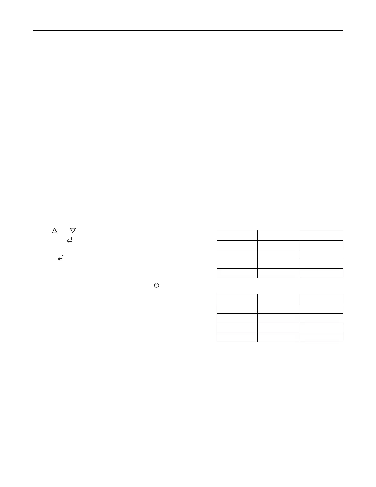
Note: Copeland ZP scroll compressors for R410A
units use Trane OIL00094. Compressor
types and appropriate oil charge is listed in
the following tables.
Table 10. Compressor types
Tonnage Compressor 1 Compressor 2
ECC180 CSHW082J0 CSHW073J0
ECC210 CSHW089J0 CSHW089J0
ECC240 ZP122KCE ZP104KCE
ECC300 ZP137KCE ZP122KCE
Table 11. POE Oil recharge amount (fl. oz.)
Tonnage Compressor 1 Compressor 2
ECC180 61 52
ECC210 61 61
ECC240 81 81
ECC300 106 81
2. After the compressor and condenser fan have started
and operated for approximately 30 minutes, observe
the operating pressures. Compare the operating
pressures to the operating pressure curve in the
Service Facts.
3. Check system subcooling. Follow the instruction listed
on the subcooling charging curve in the Service Facts.
4. Repeat Step 1 through Step 3 for each refrigerant
circuit.
5. To stop the SERVICE TEST, turn the main power
disconnect switch to the “Off” position or proceed to the
next component start-up procedure. Remove
electromechanical test mode connections (if
applicable).
Start Up