RT-SVX096A-EN
45
matched set of belts to ensure equal belt length.
When removing or installing the new belts, do not stretch
them over the sheaves. Loosen the belts using the belt
tension adjustment bolts on the motor mounting base.
Once the new belts are installed, using a Browning or
Gates tension gauge (or equivalent), adjust the belt tension
as follows:
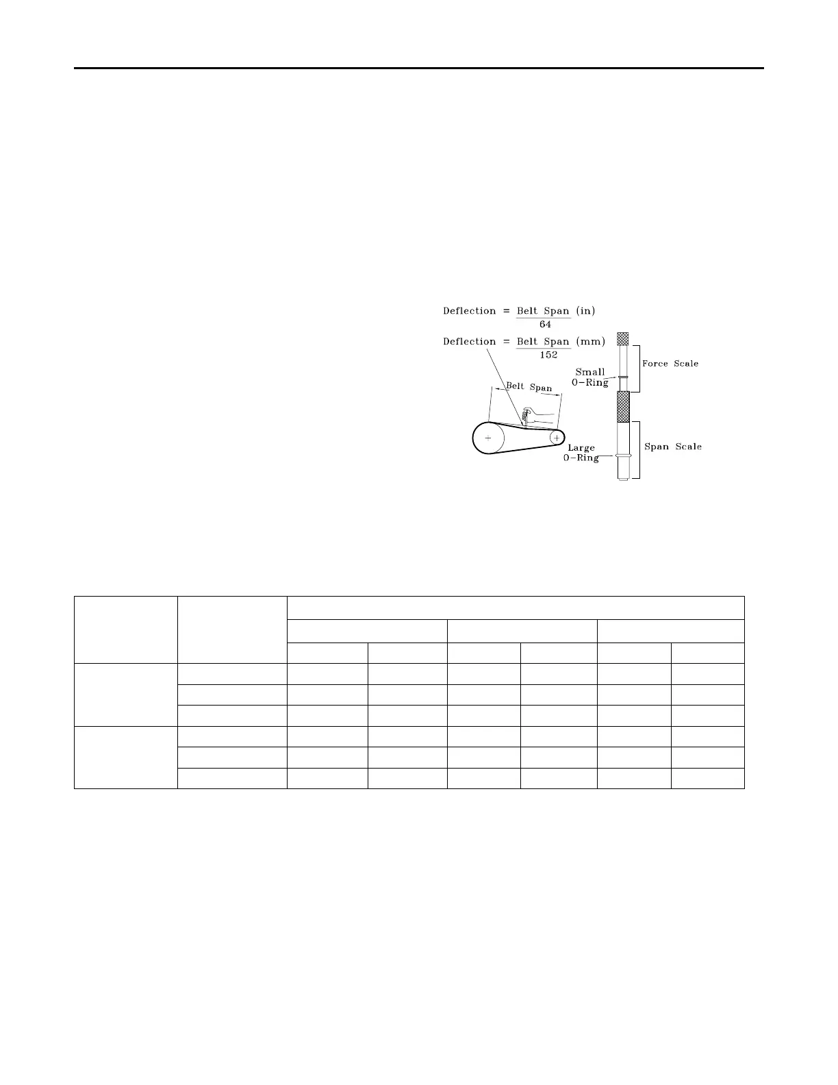
1. To determine the appropriate belt deflection:
a. Measure the center-to-center shaft distance (in
inches) between the fan and motor sheaves.
b. Divide the distance measured in Step 1a by 64; the
resulting value represents the amount of belt
deflection that corresponds to the proper belt
tension.
2. Set the large O-ring on the belt tension gauge at the
deflection value determined in Step 1b.
3. Set the small O-ring at zero on the force scale of the
gauge plunger.
4. Place the large end of the gauge at the center of the
belt span; then depress the gauge plunger until the
large O-ring is even with the top of the next belt or even
with a straightedge placed across the fan and motor
sheaves.
5. Remove the belt tension gauge. The small O-ring now
indicates a number other than zero on the plunger’s
force scale. This number represents the force (in
pounds) required to give the needed deflection.
6. Compare the “force” scale reading (Step 5) with the
appropriate “force” value listed in the Belt tension table.
If the “force” reading is outside the range, readjust the
belt tension.
Note: Actual belt deflection “force” must not exceed the
maximum “force” value shown in the Belt tension
measurement and deflection ranges table.
7. Recheck the belt tension at least twice during the first 2
to 3 days of operation. Belt tension may decrease until
the new belts are “run in”.
Figure 17. Belt tension gauge
The exhaust gas fan is that lubrication of motor, blower, or
fan bearings should not be done,and others should
Check the supply fan belts for proper tension and the fan
bearings for sufficient lubrication.
Table 17. Belt tension measurement and deflection ranges (in/lb)
Belts Cross
Section
Small P.D Range
(in)
Deflection Force (lb)
Super Gripbelts (in) Gripnotch (in) Steel Cable Gripbelts (in)
Min. Max. Min. Max Min. Max.
A
3.0–3.6 3.00 4.50 3.87 5.50 3.25 4.00
3.8–4.8 3.50 5.00 4.50 6.25 3.75 4.75
5.0–7.0 4.00 5.50 5.00 6.87 4.25 5.25
B
3.4–4.2 4.00 5.50 5.75 8.00 4.50 5.50
4.4–5.6 5.12 7.12 6.50 9.12 5.75 7.25
5.8–8.8 6.37 8.75 7.37 10.12 7.00 8.75
Maintenance