RT-SVX51H-EN
19
process. It does not replace the detailed instructions
called out in the applicable sections of this manual.
☐ Check the unit for shipping damage and material
shortage; file a freight claim and notify appropriate
sales representative.
☐ Verify correct model, options and voltage from
nameplate.
☐ Verify that the installation location of the unit will
provide the required clearance for proper
operation.
☐ Assemble and install the roof curb (if applicable).
Refer to the latest edition of the curb installers
guide that ships with each curb kit.
☐ Fabricate and install ductwork; secure ductwork to
curb.
☐ Rigging the unit.
☐ Set the unit onto the curb; check for levelness.
☐ Ensure unit-to-curb seal is tight and without buckles
or cracks.
☐ Install and connect a condensate drain line to the
evaporator drain connection.
Factory Installed Economizer
• Ensure the economizer has been pulled out into the
operating position. Refer to the standard or low leak
economizer Installation Instructions for proper
position and setup.
• Install all access panels.
Controller Wiring Schematic - LLE
For additional information, go to the Installation
Instructions ACC-SVN178*-EN.
Main Electrical Power Requirements
☐ Verify that the power supply complies with the unit
nameplate specifications.
☐ Inspect all control panel components; tighten any
loose connections.
☐ Connect properly sized and protected power supply
wiring to a field-supplied/ installed disconnect
switch and to the main power terminal block (HTB1)
in the unit control panel.
☐ Install proper grounding wires to an earth ground.
NNoottee:: All field-installed wiring must comply with NEC
and applicable local codes.
External Vent Hood Installation
NNoottee:: This procedure applies only to medium and high
heat options, not to the low heat option.
WWAARRNNIINNGG
HHaazzaarrddoouuss VVoollttaaggee!!
FFaaiilluurree ttoo ddiissccoonnnneecctt ppoowweerr bbeeffoorree sseerrvviicciinngg ccoouulldd
rreessuulltt iinn ddeeaatthh oorr sseerriioouuss iinnjjuurryy..
DDiissccoonnnneecctt aallll eelleeccttrriicc ppoowweerr,, iinncclluuddiinngg rreemmoottee
ddiissccoonnnneeccttss bbeeffoorree sseerrvviicciinngg.. FFoollllooww pprrooppeerr
lloocckkoouutt//ttaaggoouutt pprroocceedduurreess ttoo eennssuurree tthhee ppoowweerr
ccaann nnoott bbee iinnaaddvveerrtteennttllyy eenneerrggiizzeedd.. VVeerriiffyy tthhaatt nnoo
ppoowweerr iiss pprreesseenntt wwiitthh aa vvoollttmmeetteerr..
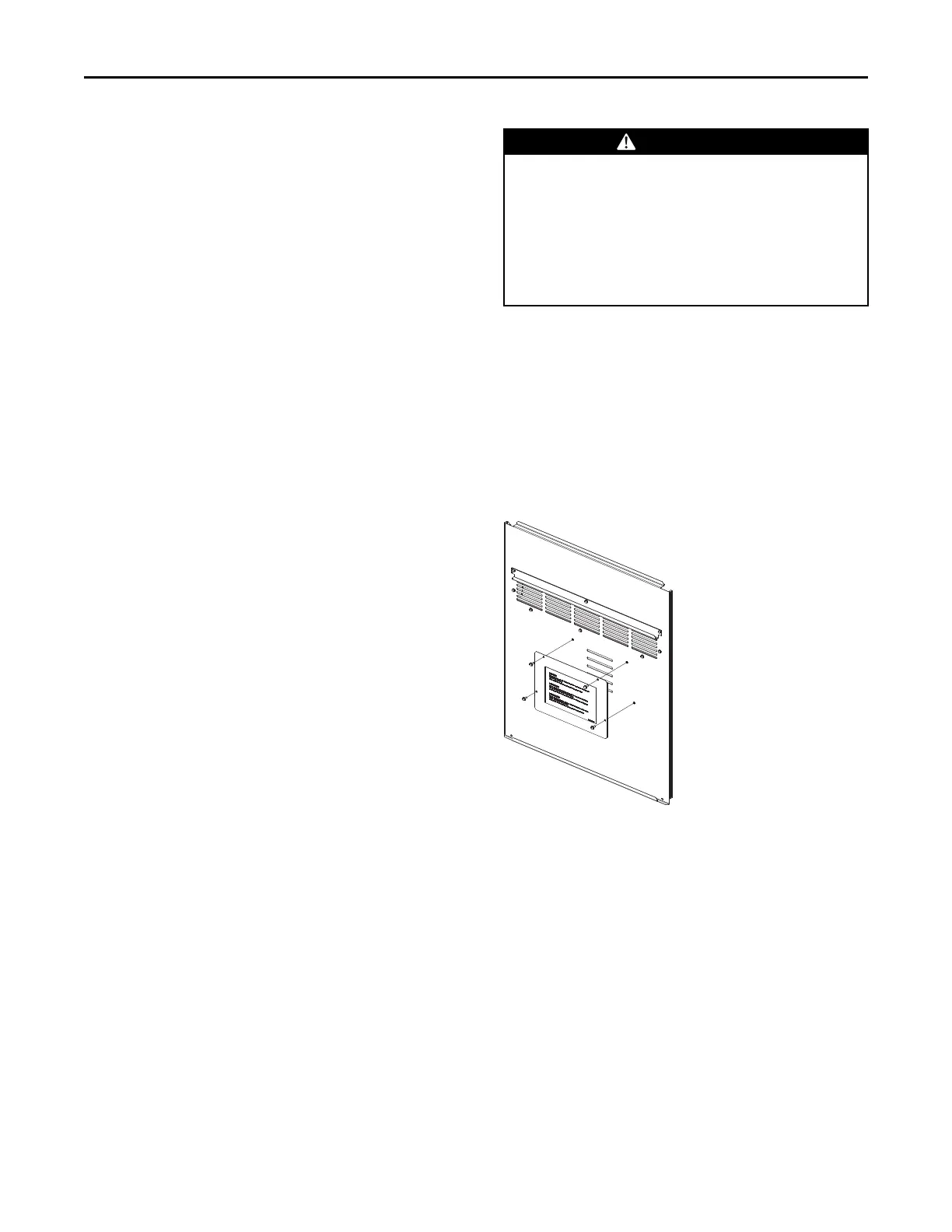
1. Remove and discard the cover plate located on the
gas heat panel.
IImmppoorrttaanntt::
• Make sure you read the label
located on the cover plate before
you discard it.
• Do not discard the fastening screws!
They will be needed to install the
vent hood.
Figure 13. Discard cover plate
2. Locate the vent hood behind the panel, on the left
side of the burner assembly.
IInnssttaallllaattiioonn