RT-SVX51H-EN
25
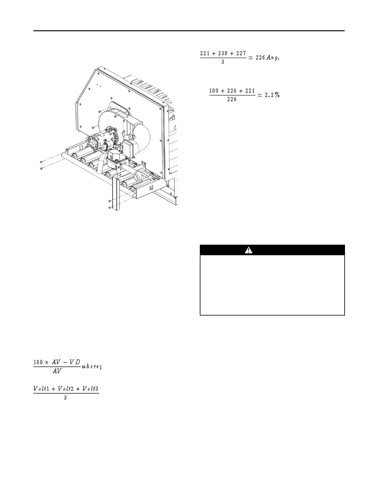
Figure 21. Typical unit gas train configuration
Voltage Imbalance
Three phase electrical power to the unit must meet
stringent requirements for the unit to operate properly.
Measure each leg (phase-to-phase) of the power
supply.
Each reading must fall within the utilization range
stamped on the unit nameplate. If any of the readings
do not fall within the proper tolerances, notify the
power company to correct this situation before
operating the unit.
Excessive three phase voltage imbalance between
phases will cause motors to overheat and eventually
fail.
The maximum allowable voltage imbalance is 2
percent. Measure and record the voltage between
phases 1, 2, and 3 and calculate the amount of
imbalance as follows:
% Voltage Imbalance =
AV (Average Voltage) =
• V1, V2, V3 = Line Voltage Readings
• VD = Line Voltage reading that deviates the farthest
from the average voltage.
Example: If the voltage readings of the supply power
measured 221, 230, and 227, the average volts would
be:
• VD (reading farthest from average) = 221
• The percentage of Imbalance equals:
The 2.2 percent imbalance in this example exceeds the
maximum allowable imbalance of 2.0 percent. This
much imbalance between phases can equal as much as
a 20 percent current imbalance with a resulting
increase in motor winding temperatures that will
decrease motor life.
If the voltage imbalance is over 2 percent, notify the
proper agencies to correct the voltage problem before
operating this equipment.
Electrical Phasing (Three Phase Motors)
The compressor motor(s) and the supply fan motor are
internally connected for the proper rotation when the
incoming power supply is phased as A, B, C.
Proper electrical supply phasing can be quickly
determined and corrected before starting the unit by
using an instrument such as an Associated Research
Model 45 Phase Sequence Indicator and following the
steps below:
WWAARRNNIINNGG
HHaazzaarrddoouuss VVoollttaaggee!!
FFaaiilluurree ttoo ddiissccoonnnneecctt ppoowweerr bbeeffoorree sseerrvviicciinngg ccoouulldd
rreessuulltt iinn ddeeaatthh oorr sseerriioouuss iinnjjuurryy..
DDiissccoonnnneecctt aallll eelleeccttrriicc ppoowweerr,, iinncclluuddiinngg rreemmoottee
ddiissccoonnnneeccttss bbeeffoorree sseerrvviicciinngg.. FFoollllooww pprrooppeerr
lloocckkoouutt//ttaaggoouutt pprroocceedduurreess ttoo eennssuurree tthhee ppoowweerr
ccaann nnoott bbee iinnaaddvveerrtteennttllyy eenneerrggiizzeedd.. VVeerriiffyy tthhaatt nnoo
ppoowweerr iiss pprreesseenntt wwiitthh aa vvoollttmmeetteerr..
1. Turn the field supplied disconnect switch that
provides power to the main power terminal block or
to the “Line” side of the optional factory mounted
disconnect switch to the “Off” position.
2. Connect the phase sequence indicator leads to the
terminal block or to the “Line” side of the optional
factory mounted disconnect switch as follows:
• Black (phase A) to L1
• Red (phase B) to L2
• Yellow (phase C) to L3
3. Close the field supplied main power disconnect
switch or circuit protector switch that provides the
supply power to the unit.
IInnssttaallllaattiioonn