18-GE20D1-1E-EN
19
Table 8. Return Duct Connections (continued)
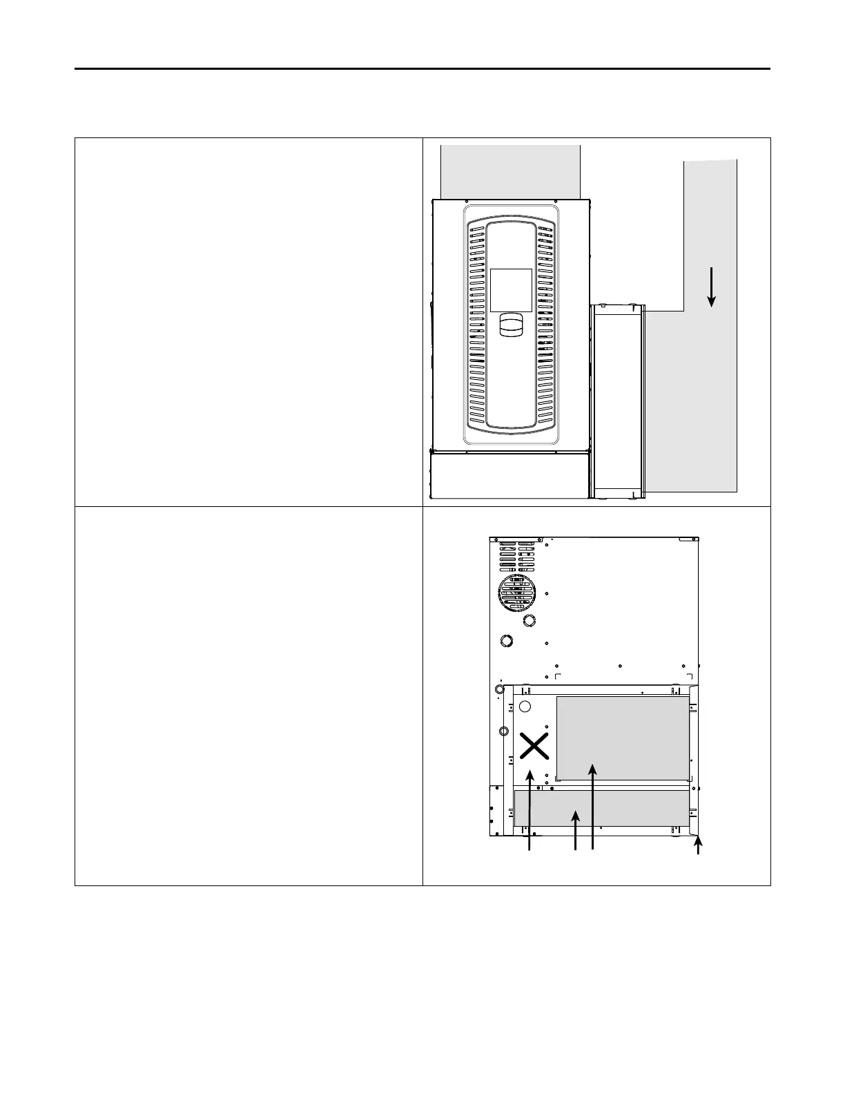
Upflow Modular Blower with Bottom and Side Returns
Mounted on a Ducted Pedestal with Side Return and Filter Box
Important: Make sure the thermostat wiring hole is sealed on the
cabinet side with the side return.
Important: Make sure not to cut the cabinet in the “No Cut” area.
Important: Remove Blower Assembly and Panel Loop before cutting
cabinet to avoid cutting wires.
1. Remove the bottom plate.
2. Create ducting and set the modular blower in place.
Note: Use Optional BAYLIFT kit to lift modular blower. Follow kit
instructions.
Note: The modular blower bottom pedestal must be a minimum of 6”
in height.
3. Match the filter cabinet flush to the back and bottom sides of the
modular blower cabinet and secure in place with screws.
4. Mark the two areas to be cut out for the return air.
5. Cut out the two sections of the cabinet and BAYLIFT kit to be
removed.
6. Attach ducting to the filter box.
7. The ducted pedestal will use ducted air from a remote location.
8. Seal per local codes and requirements.
Cabinet cutout when used with BAYLIFT
No Cut Area Cutouts
21” Filter Cabinet with BAYLIFT Kit shown
Flush with back
of furnace cabinet
GGeenneerraall IInnssttaallllaattiioonn
 Loading...