P0V0
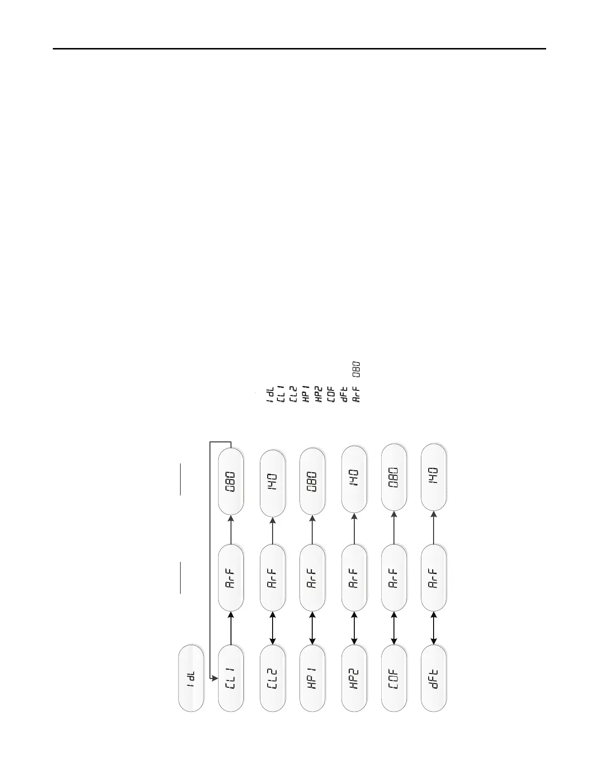
Examples of System Status
= Idle, no demand for cooling, hea!ng, or fan
= Demand for 1
st
stage cooling
= Demand for 2
nd
stage cooling
= Demand for 1
st
stage heat pump
= Demand for 2
nd
stage heat pump
= Demand for con!nuous fan
= Demand for outdoor unit defrost
/ = Calculated airflow is 800 CFM.
Airflow display is rounded down to the nearest 10 cfm
NOTES:
(1) The menu status displayed is solely dependent on the input of 24VAC
that is applied to the low voltage terminal strip.
(2) The status will alternate between the system mode and the airflow
request every 2 seconds.
(3) If an error occurs, an E*.* will alternately flash with the system mode
and airflow request.
(4)
Some units will show demand airflow while others will show calculated airflow.
Calculated airflow will gradually ramp up and may take ~1-2 minutes to stabilize.
Example
Calculated CFM
Example
Airflow
 Loading...