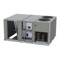
Figure 11. Reinstall end panel
Installation – FIADMPR103*
ACC-SVN231C-EN 9
Factory Installed Damper (Field
Setup)
Downflow Configuration
To position damper for downflow operation, complete the
following steps:
WARNING
Hazardous Voltage!
Failure to disconnect power before servicing could
result in death or serious injury.
Disconnect all electric power, including remote
disconnects before servicing. Follow proper lockout/
tagout procedures to ensure the power can not be
inadvertently energized. Verify that no power is present
with a voltmeter.
1. Remove filter access panel.
2. Remove the lower screws in the end panel. See Figure 12.
Lay blo
ck-off angle aside for later installation.
Figure 12. Remove lower screws
3. Do not remove the screws in the upper row of the end
p
anel.
4. Grasp the bottom of the end pan
el and pull the economizer
assembly outward into the operating position. See
Figure 12.
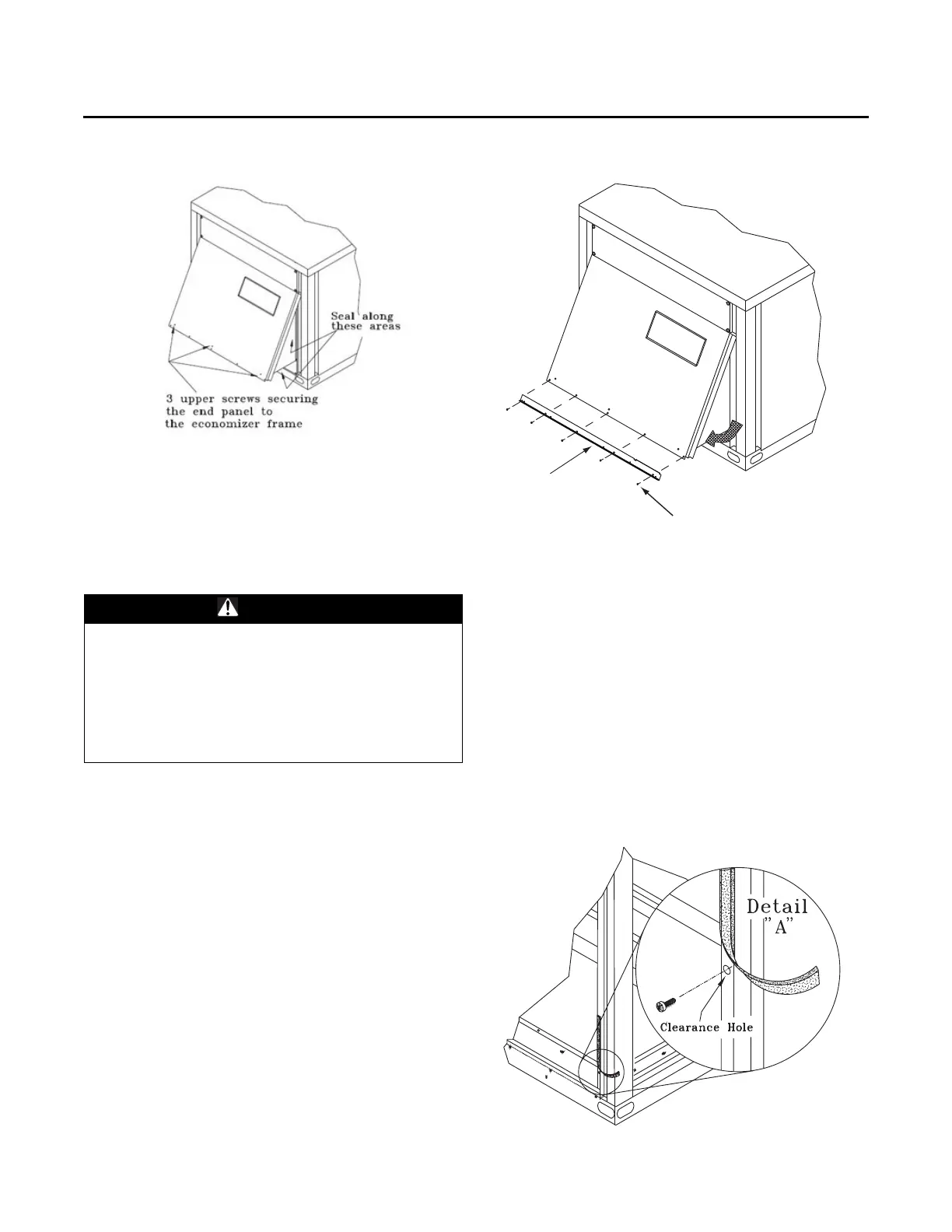
5. Remove approximately 3-inches of gasket material from
the
bottom of each corner post to expose the holes used to
attach the economizer assembly to the unit. See Figure 13.
6. With the screws provided, secure each side of the
e
conomizer assembly by inserting a screw through the
clearance hole in the bottom of the corner post and into the
engagement hole in the economizer assembly. Refer to
Figure 13.
Figure 13. Remove gasket material
Remove screws and lay blockoff
angle aside. Do not discard.
Blockoff Angle