41
PTEC-M-1A
Disassembly
Procedures
WARNING!
To avoid possible electrical shock,
personal injury or death, disconnect
the power before servicing.
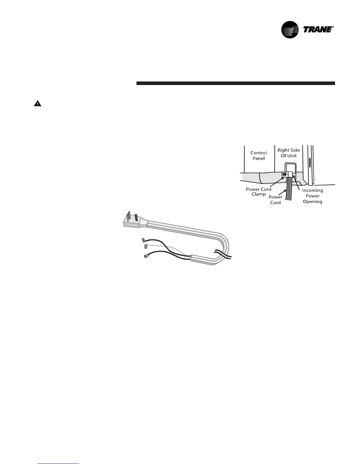
Power Cord
4. Remove the power cord clamp
located near the bottom right of
the chassis.
Incoming Power Opening
Power Cord
1. Remove the unit front by tilting the
bottom of the front outward and
then lift the front straight up.
2. Remove the control knobs on the
control panel cover by pulling
upward on the knobs. Remove the
escutcheon.
3. Remove the control panel cover
by removing the two screws
holding the control panel cover.
Tilt the control panel forward to
gain access to the wires.
Power Cord
5. On 230/208 volt units disconnect
the ribbed lead from the C
terminal on the capacitor and the
smooth lead from LINE 2 terminal
on the control board and the
green ground wire from the
partition panel.
On 265 volt units disconnect the
ribbed lead from the C terminal on
the capacitor and the smooth lead
from the fuseholder and the green
ground wire from the partition panel.