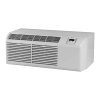
Do you have a question about the Trane PTHC-090 and is the answer not in the manual?
Records manual revisions and specific applications for technicians.
Outlines efforts to reduce refrigerant emissions during HVAC service.
Provides guidance on safely handling, storing, and disposing of refrigerants.
Details equipment for minimizing refrigerant emissions during recovery.
Discusses enhancements to reduce emissions and improve operating efficiencies.
Presents cooling capacity, EER, and airflow data for air conditioner units.
Shows cooling capacity, EER, and airflow for heat pump units with electric heat.
Describes unit functions based on mode switch settings.
Explains user controls for temperature, mode, and thermostat settings.
Details additional unit control inputs and features accessible via the control board.
Sets the operational mode for the fan based on unit operation.
Provides control inputs for a remote wall-mounted thermostat.
Details front desk switch connections to disable unit operation, preserving freeze protection.
Allows control of max heating and min cooling temps to reduce energy costs.
Allows fresh air intake for ventilation, affecting heating/cooling load.
Advises on preventing freezing of hydronic coils during shutdowns.
Explains how to adjust the air discharge grille angle.
Describes how to operate the unit with a remote thermostat.
Controls the primary heating, off, or cooling functions of the unit.
Controls whether the fan runs continuously or cycles with the unit.
Provides accurate room temperature sensing from a central location.
Instructions for cleaning the unit chassis, coils, and basepan every six months.
Guidance on cleaning the cabinet front and discharge air grille with mild detergent.
Steps to remove, clean, and reinstall the air intake filter.
Procedure for removing and cleaning the vent filter.
Illustrates the sealed system for air conditioning models.
Illustrates the sealed system for heat pump models.
Outlines essential precautions and equipment for servicing the refrigeration system.
Explains the critical process of removing moisture and air from the system.
Details methods for detecting refrigerant leaks to prevent system contamination.
Provides guidelines and accepted materials for brazing refrigeration connections.
Step-by-step procedure for achieving a thorough vacuum in the refrigeration system.
Instructions for charging the system with the correct refrigerant amount.
Final step to ensure the product performs to design standards after repair.
Precautions for observing thermometer readings during cooling performance tests.
Describes using a sling psychrometer to determine relative humidity.
Details measurements required for performing a cooling performance test.
Instructions for recording additional readings for cooling wattage tests.
Procedures for recording readings during electric heat tests.
Steps for recording wattage and temperature readings for heating performance.
Steps to check capacitor capacitance using voltage and amperage readings.
Procedure to test compressor overload protection for continuity.
How to test compressor windings for shorts, grounds, or opens.
Tests continuity of compressor start and run windings.
Checks if the compressor is grounded, indicating a need for replacement.
Wiring instructions for testing compressor start-up with a capacitor.
How to test thermistor resistance against temperature charts.
Procedures for inspecting heater elements and fuse links.
Checks if the reversing valve switches correctly between cooling and heating.
General guidelines for replacing sealed system components like compressor and coils.
Information on the thermal-operated drain pan valve for heat pump models.
Details automatic lockout, freeze protection, fan delay, and remote operation features.
Explains fuse protection on the 24-volt circuit for board safety.
Discusses thermistor function in cooling and heat pump modes.
Explains using LS & IN terminals for load shedding control.
Describes the cooling mode routine for fan operation before compressor demand.
Details connecting an auxiliary sensor to replace the indoor ambient thermistor.
Information on using a transfer fan with a user-supplied relay.
Connections for a user-supplied switch to remotely defeat unit operation.
Adding a switch to enable fan and heat, locking out compressor during power outages.
Explains LED flash codes for diagnosing control board issues.
Procedure to initiate and run the unit through its diagnostic modes.
Step-by-step guide to removing the unit's front cover.
Instructions for removing the chassis from the wall sleeve.
Procedures for removing the escutcheon, control board, and panel.
Steps to disconnect the power cord from the unit.
Instructions for removing the heater assembly from the unit.
Guide to removing the capacitor from its mounting clamp.
Steps to remove the indoor coil thermistor.
Procedure for removing the evaporator assembly.
How to remove the outdoor coil thermistor.
Instructions for removing the blower wheel, motor, and fan blade.
Steps to remove the outdoor coil assembly.
Procedure for removing the compressor from the unit.
Instructions for removing the reversing valve.
Steps to remove the drain valve.
Procedure for removing the vent door.
Table showing wattage ranges for air conditioners under various temperature conditions.
Table showing wattage ranges for heat pumps under various temperature conditions.
Table showing temperature difference across indoor coil for AC units.
Presents amperage ranges for AC units based on inlet air temperature.
Table showing wattage ranges for heat pumps under various temperature conditions.
Table showing temperature difference across indoor coil for heat pumps.
Wiring diagram for standard units with one stage heat and added controls.
Wiring diagram for standard units with two stage heat and added controls.
Wiring diagram for units with condensate pump and one stage heat.
Wiring diagram for units with condensate pump and two stage heat.
Wiring diagram for units with power vent and one stage heat.
Wiring diagram for units with power vent and two stage heat.
Wiring diagram for units with power door and one stage heat.
Wiring diagram for units with power door and two stage heat.
Wiring diagram for units with condensate pump, power vent, and one stage heat.
Wiring diagram for units with condensate pump, power vent, and two stage heat.
Wiring diagram for hydronic models, illustrating connections and components.
| Brand | Trane |
|---|---|
| Model | PTHC-090 |
| Category | Air Conditioner |
| Language | English |