Do you have a question about the Trane PTEC-150 and is the answer not in the manual?
Policy to reduce refrigerant emissions during HVAC service and maintenance operations.
Explains the alphanumeric code for Packaged Terminal Air Conditioners.
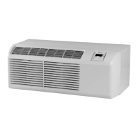
Describes unique unit features and lists optional accessories for installation.
Explains mode switch settings and user-operated controls.
Details master, remote, fan cycle, and front desk control functions.
Guides on using remote thermostats and sensors for unit operation.
Instructions for cleaning the chassis, intake filter, and vent filter.
Information on compressor/fan motor and cabinet front cleaning.
Illustrates the refrigeration cycle for air conditioning and heat pump models.
Outlines general warnings and requirements for servicing the refrigeration system.
Details critical procedures for system integrity and refrigerant handling.
Guides on conducting cooling and heating performance tests using specific procedures.
Procedures for testing capacitors and compressor electrical components.
Guides on testing thermistors, heaters, and reversing valve operation.
Outlines general practices for replacing sealed system components.
Explains features like compressor lockout, freeze protection, and fan delays.
Details remote thermostat, sensor integration, and front desk control.
Covers LED flash codes for error detection and the self-diagnostic routine.
Steps for removing the unit's front cover and sliding out the chassis.
Procedures for accessing power cord, capacitor, heater assembly, and control board.
Details disassembly of the condenser, compressor, reversing valve, and drain valve.
Tables for cooling wattage, amperage, and temperature change for AC and heat pump models.
Tables for heating wattage and temperature change for heat pump models.
Wiring schematics for standard, two-stage, and heat pump units.
Schematics for units with condensate pump, power vent, and power door features.
Wiring schematic specific to hydronic unit configurations.
| Brand | Trane |
|---|---|
| Model | PTEC-150 |
| Category | Air Conditioner |
| Language | English |