Do you have a question about the Trane PTEC-070 and is the answer not in the manual?
Discusses the company's policy on reducing refrigerant emissions and responsible handling.
Provides guidelines and safety precautions for handling refrigerants.
Details recommended equipment and procedures for minimizing refrigerant emissions.
Information on upcoming unit enhancements and refrigerant-compatible parts.
Explains the alphanumeric identification code for model numbers and their components.
Breaks down the chassis model number into its constituent parts and their meanings.
General advice for servicing products, emphasizing qualified technicians and proper tools.
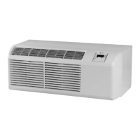
Highlights unique features of the unit compared to conventional PTAC units.
Lists optional accessories required or recommended for complete installation.
Presents cooling performance data for air conditioner models.
Presents cooling performance data for heat pump models.
Provides reverse cycle heating capacity data for heat pump models.
Details electric heat capacity and electrical requirements for models.
Shows different power receptacle configurations for various voltage ratings.
Critical safety warning regarding electrical hazards during service.
Explains user controls for temperature setting and operational mode selection.
Details on setting the thermostat and operating the mode switch.
Describes the function of the master switch and remote/standard switch.
Explains fan cycle operation and front desk control interface.
Details the temperature limiting feature for energy cost reduction.
Information on vent control operation and hydronic heat installation risks.
Guidance on adjusting the air discharge grille for optimal airflow.
Procedure for setting up the unit to operate with a remote thermostat.
Recommendations for optimal placement of remote thermostats.
Explains the function of the HEAT/OFF/COOL and Fan switches.
Details the remote temperature sensor accessory and its connection.
Procedures for cleaning the chassis, compressor, fan motor, and cabinet front.
Instructions for cleaning and replacing the intake air filter.
Step-by-step guide for cleaning the vent filter.
Illustrates the refrigeration system components for PTEC units.
Shows refrigeration system diagrams for heat pump models.
Safety warnings and important notes for servicing the refrigeration system.
Procedures for dehydrating the system and testing for refrigerant leaks.
Details on proper brazing techniques and accepted materials.
Step-by-step guide for evacuating the refrigeration system thoroughly.
Instructions for charging the system with refrigerant and performing tests.
Ensuring correct operation and the importance of the wall sleeve.
Guidelines for using thermometers and a sling psychrometer for testing.
Details on calculating temperature differences from test readings.
Procedure for conducting cooling wattage tests and their calculations.
Steps for performing an electric heat test on the unit.
Instructions for conducting heating wattage tests.
Detailed steps for checking capacitor resistance using an ohmmeter.
Tests for capacitor health and overload protection continuity.
Procedure to test compressor windings for continuity and shorts.
Testing the compressor for grounding issues using an ohmmeter.
Tests for the heater assembly and the reversing valve operation.
General guidelines and practices for replacing sealed system components.
Details on features like compressor lockout, freeze protection, and delays.
Information on remote controls, fuse protection, and thermistor functions.
Describes thermistor functions and the use of load shedding terminals.
Explains diagnostic routines, remote sensors, transfer fans, and front desk controls.
Lists flash codes for on-board diagnostics and their corrective actions.
Step-by-step procedure to initiate and run the self-diagnostic mode.
Critical safety warning before performing any disassembly.
Steps for removing the front cover and the main chassis.
Procedure for removing the escutcheon, control board, and associated panel.
Instructions for safely disconnecting the power cord from the unit.
Steps for removing the capacitor and the heater assembly.
Procedures for removing the indoor coil thermistor and evaporator.
Steps for removing the outdoor coil thermistor and blower assembly.
Procedures for removing the condenser coil and the compressor.
Instructions for removing the reversing valve, drain valve, and vent door.
Tables showing cooling wattage input ranges for air conditioner models.
Tables showing cooling wattage input ranges for heat pump models.
Data on temperature changes across the indoor coil for cooling operation.
Charts detailing cooling amperage input ranges for various models.
Data on heating wattage and temperature changes for performance analysis.
Wiring diagram for standard units with one stage heat and added controls.
Wiring diagram for standard units with two stage heat and added controls.
Wiring diagram for units with condensate pump and one stage heat.
Wiring diagram for units with condensate pump and two stage heat.
Wiring diagram for units with power vent and one stage heat.
Wiring diagram for units with power vent and two stage heat.
Wiring diagram for units with power door and one stage heat.
Wiring diagram for units with power door and two stage heat.
Wiring diagram for units with condensate pump, power vent, and one stage heat.
Wiring diagram for units with condensate pump, power vent, and two stage heat.
Wiring diagram for hydronic unit configurations.
| Model | PTEC-070 |
|---|---|
| Type | Packaged Terminal Air Conditioner |
| Cooling Capacity | 7, 000 BTU/h |
| Voltage | 115V |
| Dimensions | 42" H x 16" W x 16" D |
| Phase | 1 |
| Refrigerant | R-410A |