Do you have a question about the Trane PTEC-120 and is the answer not in the manual?
Details on manual revisions and intended use for experienced technicians.
Guidance on minimizing refrigerant emissions during HVAC service operations.
Recommendations for equipment and methods to minimize refrigerant emissions.
Explanation of alphanumeric model codes for unit identification.
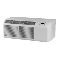
Description of unique features differing from conventional PTAC units.
List of optional accessories for completing PTAC installations.
Tables detailing cooling capacity, EER, and airflow for various models.
Electrical data for electric heat and power receptacle configurations.
Explanation of mode switch positions and user control knobs.
Details on operating the thermostat and setting room temperature.
Information on front desk switch and remote thermostat terminal connections.
How to configure DIP switches to control heating and cooling temperature limits.
Instructions for using the vent control and adjusting discharge grille angles.
Guidelines for optimal thermostat placement and remote operation.
Description of heat/off/cool and fan switch functions.
Details on the remote temperature sensing accessory for accurate room sensing.
Procedures for cleaning the unit's chassis and cabinet front.
Instructions for removing, cleaning, and reinstalling intake and vent filters.
Safety precautions and general requirements for refrigeration system service.
Procedures and materials for leak testing, brazing, and system integrity.
Step-by-step guide for evacuating and charging the refrigeration system.
Methods for conducting cooling performance tests using thermometers.
How to test capacitor resistance and compressor overloads.
Procedures for testing compressor windings and ground continuity.
Methods for testing heater elements and reversing valve operation.
General procedures for replacing sealed system components like compressor and coils.
Description of control board features like compressor lockout and fan delay.
Information on LED flash codes for diagnosing control board issues.
Step-by-step guide to initiate and run the unit's self-diagnostic mode.
Instructions for safely removing the front cover and the unit chassis.
Steps for accessing and disconnecting the control board and related wiring.
Procedures for removing key components like heater, evaporator, and condenser.
Steps for removing the compressor and blower motor assembly.
Tables correlating outdoor/indoor air conditions with wattage and amperage.
Charts detailing heating wattage based on various temperature conditions.
Wiring diagrams for standard and heat pump units.
Wiring diagrams for units with condensate pump and power vent.
Wiring diagrams for power door and two-stage heat units.
| Brand | Trane |
|---|---|
| Model | PTEC-120 |
| Category | Air Conditioner |
| Language | English |