TRANE
R
19
Assembly & Installation
Piping - Condensate Drain
Pan Connections
On cooling section(s) the drain pan
should always be connected directly
to a trap to ensure proper drainage of
condensate.
Male-threaded, 1-1/2" BSPT conden-
sate drain connection is provided on
one side of the coil section. The main
drain lines and trap must be the same
size as the drain connection.
Pitch the connection line horizontal or
downward toward an open drain and
install a plugged tee to facilitate
cleaning. Condensate lines should not
be connected to a closed drain. This
is to avoid the possibility of drawing
sewer gasses into the unit.
Drain traps must be primed. lf they
are not, the trap is essentially non-
existent and the drain pan will likely
overflow.
CAUTION
!
Units With More Than One
Drain Pan
With the Trane Quantum
TM
Air Handler,
each module can be ordered with or
without a drain pan.
When more than
one module has a drain pan, you must
trap each module individually.
Connecting all drains to a common line
with only one trap will result in
condensate retention, and possible
water damage to the air handler or
adjoining space.
If a module has a drain pan for cleaning
purposes only, it does not need a trap;
however a cap or shut off valve should
be installed on the drain connection.
Only modules handling condensate,
such as a cooling coil module or
eliminator module, require a trap.
Figure 9
through
Figure 10
are
examples of typical installations.
IMPORTANT
!
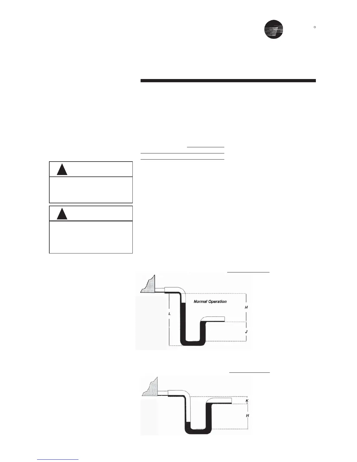
Figure 9
Drain Pan Trapping for module under Negative Pressure
H = (1” for each 1” of
maximum negative
pressure) + 1”
J = 1/2 H
L = H + J + Pipe diameter +
Insulation
Figure 10
Drain Pan Trapping for module under Positive Pressure
K = min. 1/2”
H = 1/2” plus maximum
total static pressure
Failure to provide adequate
condensate piping may result in
water damage to the equipment or
building.
The applicable "rule of thumb" for
amount of condensate may as high
as 6 lbs/hr/ton for units serving areas
with high latent heat.