Unit Wiring
RTAC-SVX01J-EN 169
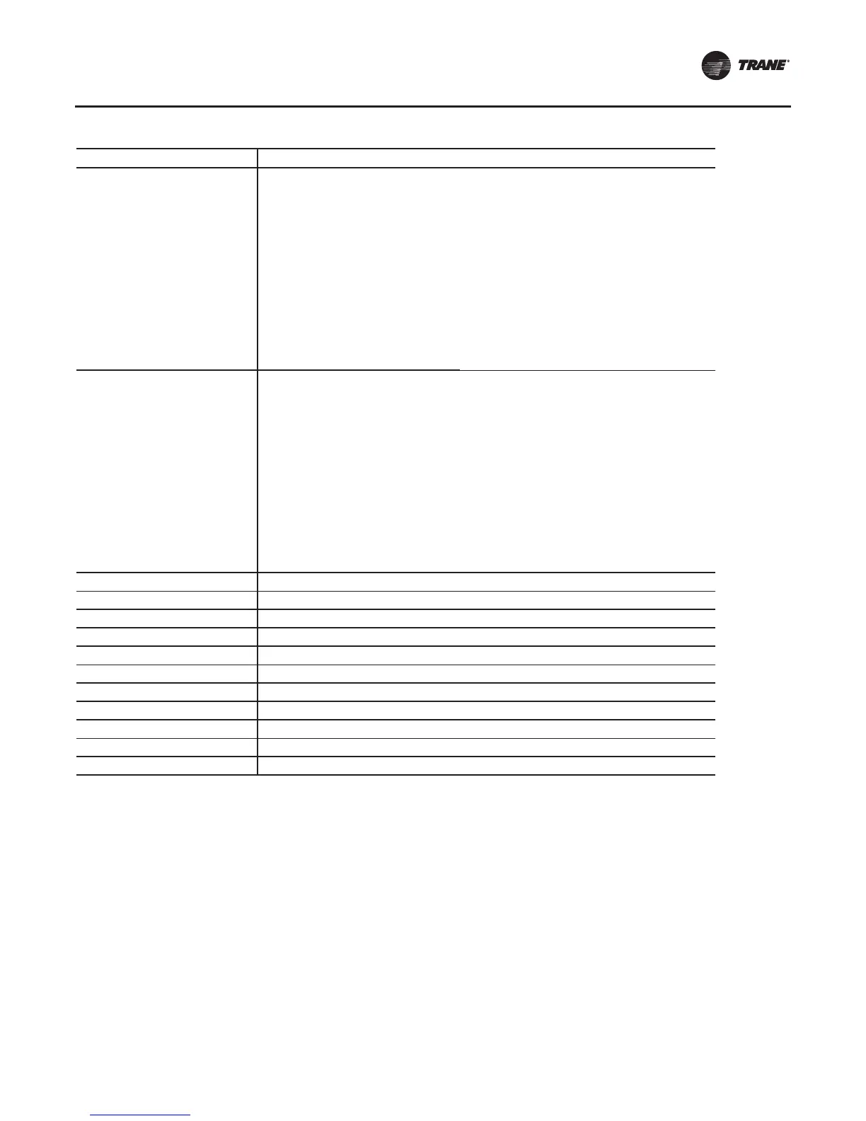
2309-4623
Sheet 1
Schematic - 4 Compressor Units
X-Line
Table of Contents & Notes
Sheet 2 Devices, Descriptions & Designations
Sheet 3 Compressor Power 1A & Fan Control Ckt 1
Sheet 4 Compressor Power 1B
Sheet 5 Compressor Power 2A & Fan Control Ckt 2
Sheet 6 Compressor Power 2B
Sheet 7 Fan Power Circuit 1
Sheet 8 Fan Power Circuit 2
Sheet 9 Common Control - Panel LLIDs
Sheet 10 Common Control - Panel LLIDs
Sheet 11 Common Control - Panel LLIDs
2309-4624
Sheet 1
Schematic - 4 Compressor
Y-Delta
Table of Contents & Notes
Sheet 2 Devices, Descriptions & Designations
Sheet 3 Compressor Power 1A & Fan Control Ckt 1
Sheet 4 Compressor Power 1B
Sheet 5 Compressor Power 2A & Fan Control Ckt 2
Sheet 6 Compressor Power 2B
Sheet 7 Fan Power Circuit 1
Sheet 8 Fan Power Circuit 2
Sheet 9 Common Control - Panel LLIDs
Sheet 10 Common Control - Panel LLIDs
Sheet 11 Common Control - Panel LLIDs
2309-4871 Component Location 2 Compressor Units
2309-4874 Component Location 3 Compressor Units
2309-4873 Component Location 4 Compressor Units
2309-4872 Component Location 2 Compressor - Optional Remote Evaporator
2309-2248 Field Layout 2 Compressor Units
2309-2239 Field Layout 3 or 4 Compressor Units
2309-2208 Field Wiring; RTAC, 2 Compressor Units 2 Compressor Units
2309-2223 Field Wiring 3 or 4 Compressor Units, Single Source Power
2309-2222 Field Wiring 3 or 4 Compressor Units, Dual Source Power
2309-7572 Sequence of Operation 2 Compressor Units
2309-7581 Sequence of Operation 3 or 4 Compressor Units
Table 70. RTAC unit wiring drawing numbers
Drawing Number Description
 Loading...


