Installation - Mechanical
44 RTAC-SVX01J-EN
Isolation and Sound Emission
The most effective form of isolation is to locate the unit
away from any sound sensitive area. Structurally
transmitted sound can be reduced by elastomeric
vibration eliminators. Spring isolators are not
recommended. Consult an acoustical engineer in critical
sound applications.
For maximum isolation effect, isolate water lines and
electrical
conduit.Wall sleeves and rubber isolated piping
hangers can be used to reduce the sound transmitted
through water piping.To reduce the sound transmitted
through electrical conduit, use flexible electrical conduit.
State and local codes on sound emissions should always
be
considered. Since the environment in which a sound
source is located affects sound pressure, unit placement
must be carefully evaluated. Sound power levels forTrane
air-cooled Series R
®
chillers are available on request.
Unit Isolation and Leveling
For additional reduction of sound and vibration, install the
optional neoprene isolators.
Construct an isolated concrete pad for the unit or provide
concrete footings at the unit mounting points. Mount the
unit directly to the concrete pads or footings.
Level the unit using the base rail as a reference.The unit
must
be level within 1/4-in (6 mm) over the entire length
and width. Use shims as necessary to level the unit.
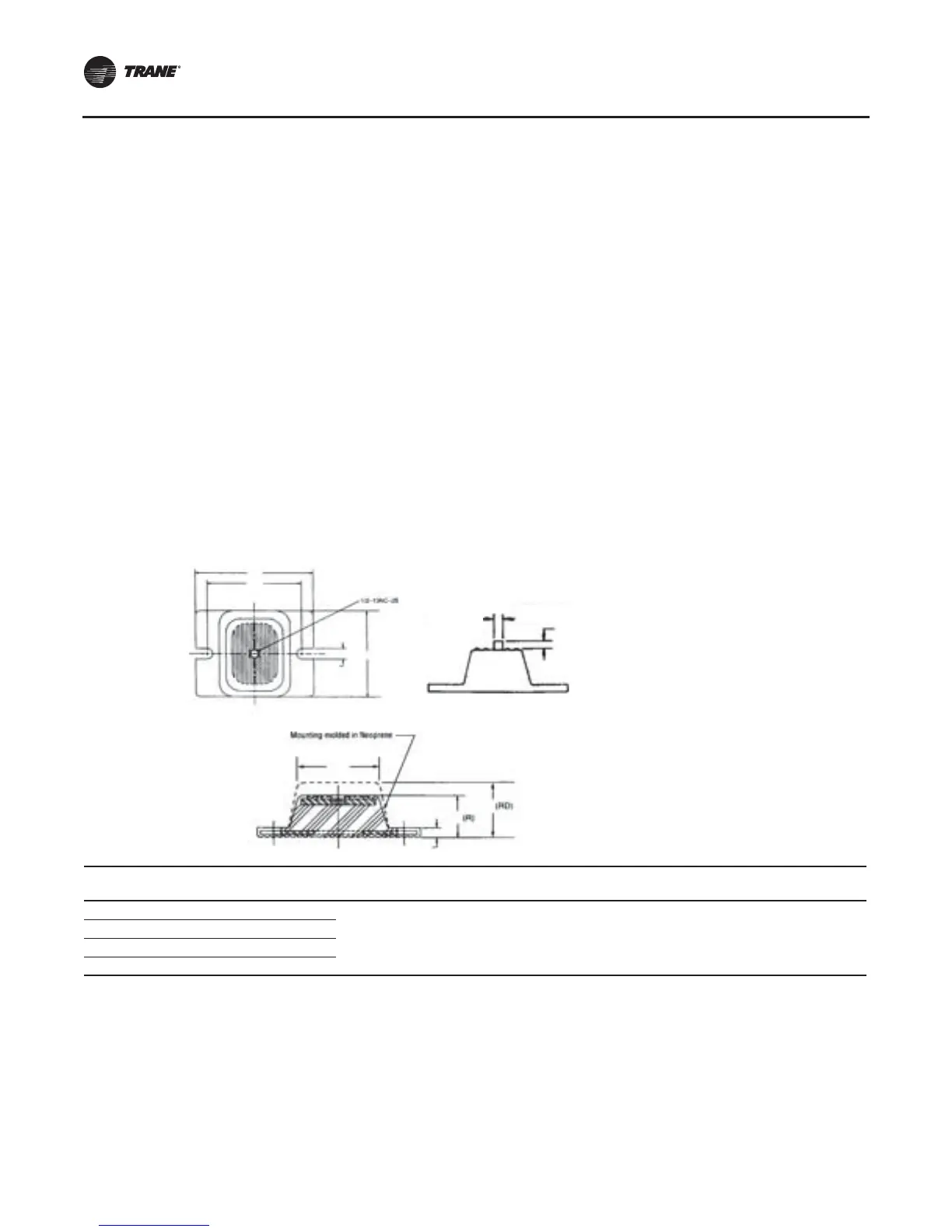
Neoprene Isolator Installation
1. Secure the isolators to the mounting surface using the
mounting slots in the isolator base plate. Do not fully
tighten the isolator mounting bolts at this time.
2. Align the mounting holes in the base of the unit with
the
threaded positioning pins on the top of the
isolators.
3. Lower the unit onto the isolators and secure the
isolator
to the unit with a nut. Maximum isolator
deflection should be 1/4 inch (6 mm).
4. Level the unit carefully. Fully tighten the isolator
mounting
bolts.
EXT
Max Load Each
(lbs) Color
Deflection
(in) A B C D E H L M W Type
61 1500 BROWN
0.50 3.00 0.50 5.00 0.56 0.38 2.75 6.25
1.60±
.25
4.63 RDP-4
62 2250 RED
63 3000 GREEN
64 4000 GRAY
Figure 16. RTAC elastomeric isolator
D
W
L
C
H
H
E
A
« B » Dia
RP/RDP
« M »
 Loading...


