168 RTAC-SVX01J-EN
Unit Wiring
Table 70 provides a list of field wiring diagrams, electrical schematics and connection diagrams for 120-500 ton RTAC
units.The complete unit wiring package is documented in RTAC-SVE01*-EN. A laminated wiring diagram kit is also
shipped with each RTAC unit.
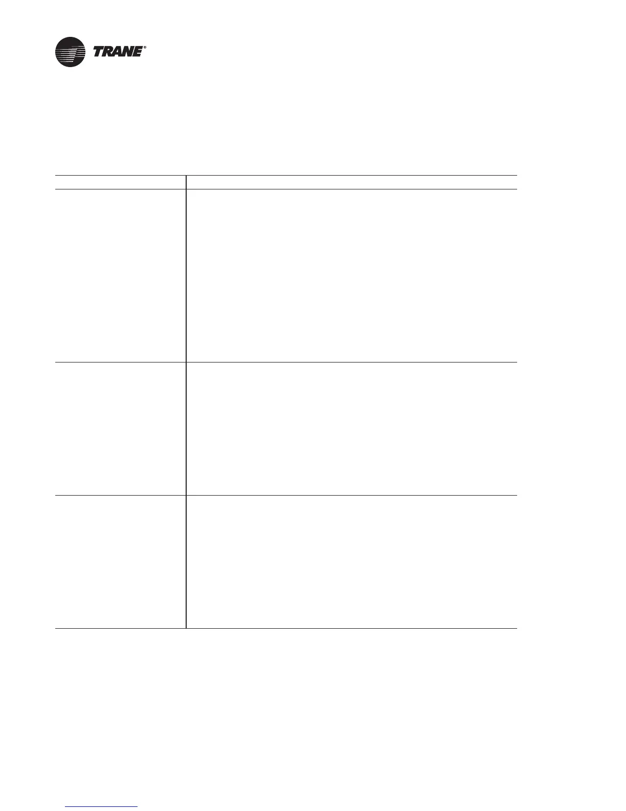
Table 70. RTAC unit wiring drawing numbers
Drawing Number Description
2309-2097
Sheet 1
Schematic - 2 Compressor Units
Table of Contents & Notes
Sheet 2 Legend
Sheet 3 (X-Line) Compressor 1A (X-Line)
Sheet 3 (Y-Delta) Compressor 1A (Y-delta)
Sheet 4 (X-Line) Compressor 2A (X-Line)
Sheet 4 (Y-Delta) Compressor 2A (Y-delta)
Sheet 5 Fans, Std & Prem, Medium Air Cooled
Sheet 6 Fans, 140 & 155 Std, 120 & 130 Prem 50 Hz
Sheet 7 Fans 225, 250 Prem 60 Hz, 185 & 200 Extra 60 Hz
Sheet 8 VSD Fans - Circuits 1 & 2
Sheet 9 Controls
Sheet 10 LLID Bus
Sheet 11 Remote Evaporator
2309-4621
Sheet 1
Schematic - 3 Compressor Units,
X-Line
Table of Contents & Notes
Sheet 2 Devices, Descriptions & Designations
Sheet 3 Compressor Power 1A & Fan Control Ckt 1
Sheet 4 Compressor Power 1B
Sheet 5 Compressor Power 2A & Fan Control Ckt 2
Sheet 6 Fan Power Circuit 1
Sheet 7 Fan Power Circuit 2
Sheet 8 Common Control - Panel LLIDs
Sheet 9 Common Control - Panel LLIDs
Sheet 10 Common Control - Panel LLIDs
2309-4622
Sheet 1
Schematic - 3 Compressor, Units
Y-Delta
Table of Contents & Notes
Sheet 2 Devices, Descriptions & Designations
Sheet 3 Compressor Power 1A & Fan Control Ckt 1
Sheet 4 Compressor Power 1B
Sheet 5 Compressor Power 2A & Fan Control Ckt 2
Sheet 6 Fan Power Circuit 1
Sheet 7 Fan Power Circuit 2
Sheet 8 Common Control - Panel LLIDs
Sheet 9 Common Control - Panel LLIDs
Sheet 10 Common Control - Panel LLIDs
 Loading...


