SS-SVX11K-EN
65
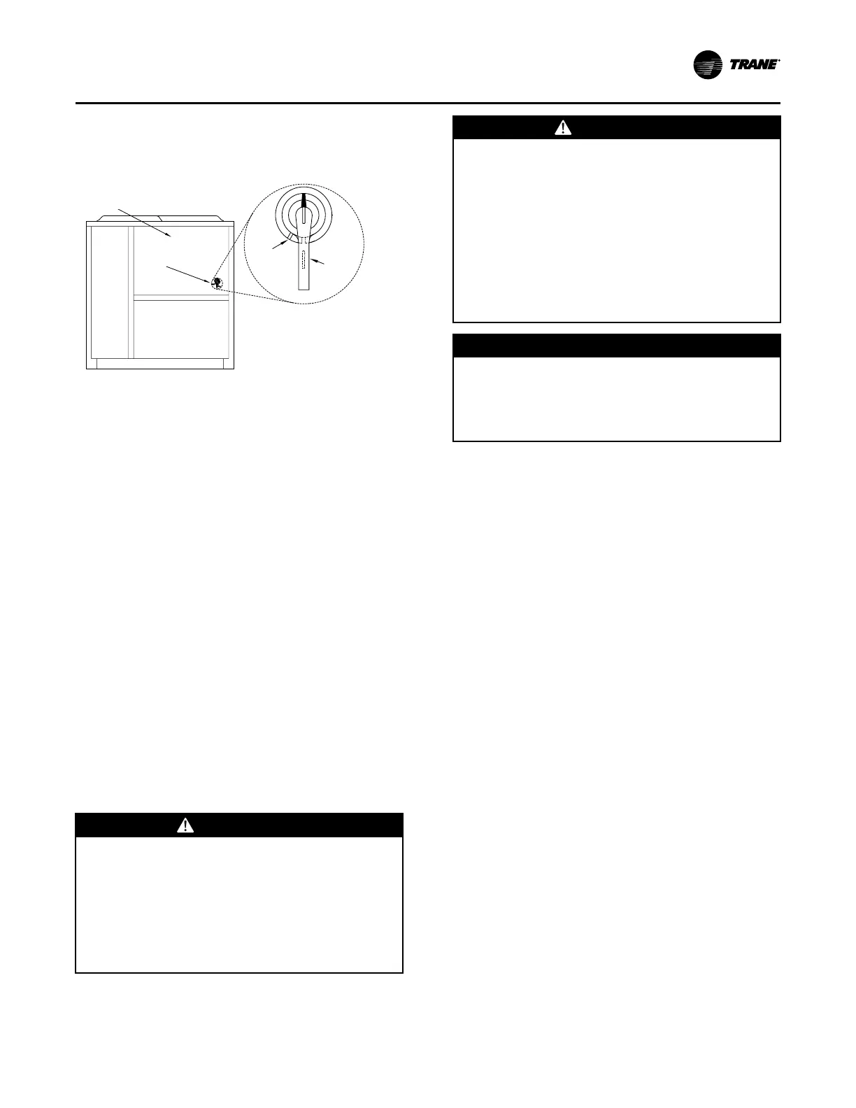
Disconnect Switch External Handle
(Factory Mounted Option)
Figure 43. Disconnect switch details
Control Box Door
Disconnect
Switch
External
Handle
Locking
Slot
Locking
Thumb Key
Under Handle
Units ordered with the factory mounted nonfused
disconnect switch comes equipped with an externally
mounted handle. This allows the operator to
disconnect power from the unit without having to open
the control panel door. Handle locations and its three
positions are shown below:
• “ON” - Indicates disconnect switch is closed,
allowing main power supply to be applied at unit.
• “OFF” - Indicates disconnect switch is open,
interrupting main power supply to unit controls.
• “OPEN COVER/RESET” - Turning the handle to this
position releases the handle form the disconnect
switch, allowing the control panel door to be
opened.
Once the door has been opened, it can be closed with
the handle in any one of the three positions outlined
above, provided it matches the disconnect switch
position.
The handle can be locked in the “OFF” position. While
holding the handle in the “OFF” position, push the
spring loaded thumb key, attached to the handle, into
the base slot. Place the lock shackle between the
handle and the thumb key. This will prevent it from
springing out of position.
Main Unit Power Wiring
WWAARRNNIINNGG
HHaazzaarrddoouuss VVoollttaaggee!!
FFaaiilluurree ttoo ddiissccoonnnneecctt ppoowweerr bbeeffoorree sseerrvviicciinngg ccoouulldd
rreessuulltt iinn ddeeaatthh oorr sseerriioouuss iinnjjuurryy..
DDiissccoonnnneecctt aallll eelleeccttrriicc ppoowweerr,, iinncclluuddiinngg rreemmoottee
ddiissccoonnnneeccttss bbeeffoorree sseerrvviicciinngg.. FFoollllooww pprrooppeerr
lloocckkoouutt//ttaaggoouutt pprroocceedduurreess ttoo eennssuurree tthhee ppoowweerr
ccaann nnoott bbee iinnaaddvveerrtteennttllyy eenneerrggiizzeedd.. VVeerriiffyy tthhaatt nnoo
ppoowweerr iiss pprreesseenntt wwiitthh aa vvoollttmmeetteerr..
WWAARRNNIINNGG
PPrrooppeerr FFiieelldd WWiirriinngg aanndd GGrroouunnddiinngg
RReeqquuiirreedd!!
FFaaiilluurree ttoo ffoollllooww ccooddee ccoouulldd rreessuulltt iinn ddeeaatthh oorr
sseerriioouuss iinnjjuurryy..
AAllll ffiieelldd wwiirriinngg MMUUSSTT bbee ppeerrffoorrmmeedd bbyy qquuaalliiffiieedd
ppeerrssoonnnneell.. IImmpprrooppeerrllyy iinnssttaalllleedd aanndd ggrroouunnddeedd
ffiieelldd wwiirriinngg ppoosseess FFIIRREE aanndd EELLEECCTTRROOCCUUTTIIOONN
hhaazzaarrddss.. TToo aavvooiidd tthheessee hhaazzaarrddss,, yyoouu MMUUSSTT ffoollllooww
rreeqquuiirreemmeennttss ffoorr ffiieelldd wwiirriinngg iinnssttaallllaattiioonn aanndd
ggrroouunnddiinngg aass ddeessccrriibbeedd iinn NNEECC aanndd yyoouurr llooccaall//
ssttaattee//nnaattiioonnaall eelleeccttrriiccaall ccooddeess..
NNOOTTIICCEE
UUssee CCooppppeerr CCoonndduuccttoorrss OOnnllyy!!
FFaaiilluurree ttoo uussee ccooppppeerr ccoonndduuccttoorrss ccoouulldd rreessuulltt iinn
eeqquuiippmmeenntt ddaammaaggee aass tthhee eeqquuiippmmeenntt wwaass nnoott
ddeessiiggnneedd oorr qquuaalliiffiieedd ttoo aacccceepptt ootthheerr ttyyppeess ooff
ccoonndduuccttoorrss..
See “Power Wire Sizing and Protection Devices,” p. 66
for field connection wire ranges for main power
terminal block 1TB1 and optional disconnect switch
1S1.
See Electrical Data tables for unit electrical data. The
electrical service must be protected from over current
and short circuit conditions in accordance with NEC
requirements. Protection devices must be sized
according to the electrical data on the nameplate.
• See Calculation — MCA, MOP, and RDE in “Wiring
Requirements,” p. 63 section to determine the
following:
– Electrical service wire size based on Minimum
Circuit Ampacity (MCA),
– Maximum Overcurrent Protection (MOP) device.
– Recommended Dual Element fuse size (RDE).
• If the unit is not equipped with an optional factory
installed non-fused disconnect switch, a field
supplied disconnect switch must be installed at or
near the unit in accordance with the National
Electrical Code (latest edition). See Calculation —
Disconnect Switch Sizing (DSS) in “Wiring
Requirements,” p. 63 section to determine the
correct size.
• Complete the unit’s power wiring connections onto
either the main terminal block 1TB1, or the factory
mounted non-fused disconnect switch 1S1, inside
the unit control panel. Refer to the customer
connection diagram that shipped with the unit for
specific termination points.
• Provide proper grounding for the unit in accordance
with local and national codes.
IInnssttaallllaattiioonn EElleeccttrriiccaall