RLC-SVX19A-E4
43
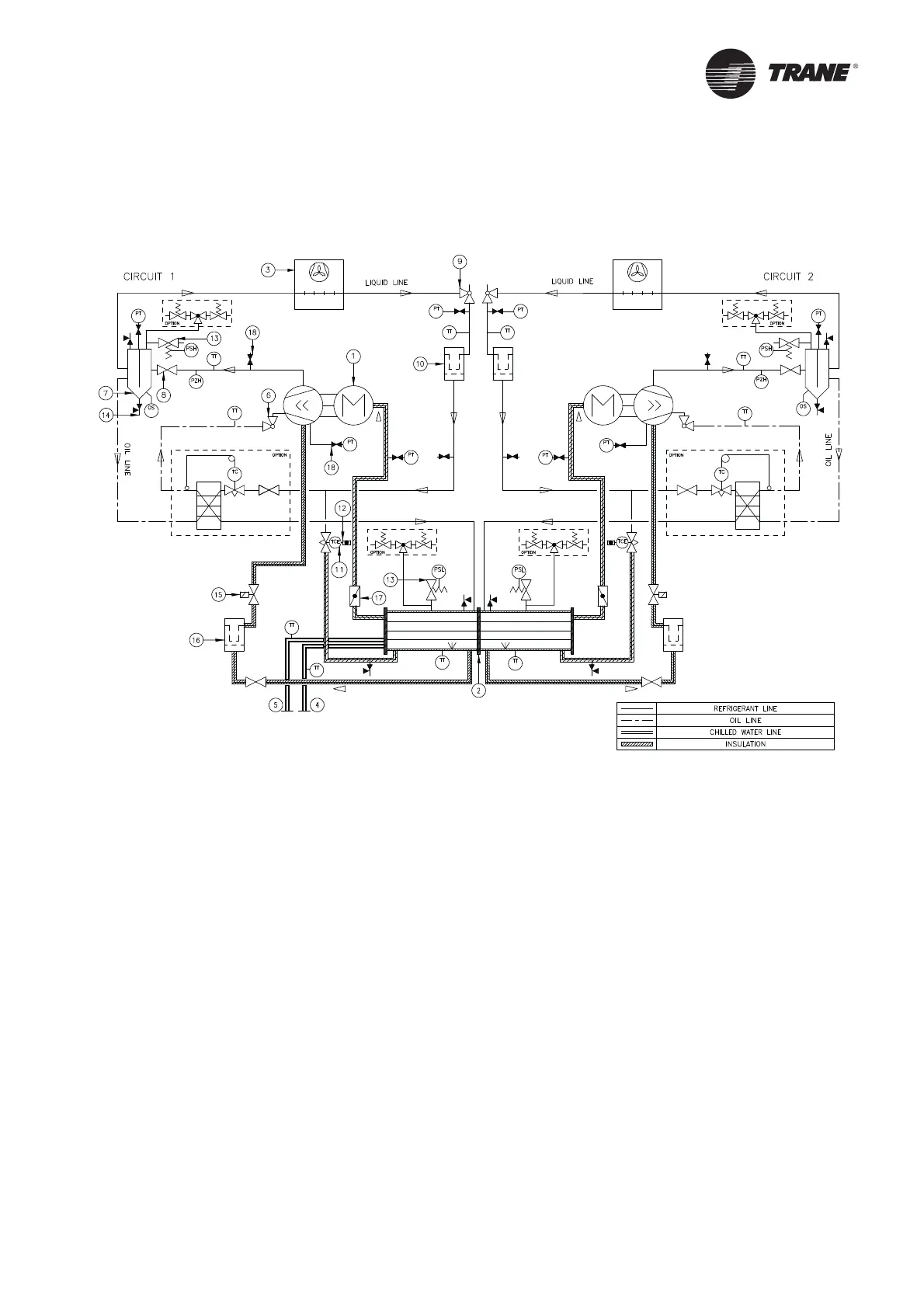
Operating Principles
This section describes the overall operating principle of the RTAF design.
Figure 20 – Refrigerant System Schematic & Oil Lube Circuit Schematic
1 = Screw compressor
2 = Evaporator
3 = Air-cooled condenser
4 = Evaporator water inlet connection
5 = Evaporator water outlet connection
6 = Oil service valve
7 = Oil separator
8 = Discharge service valve
9 = Liquid shut off valve
10 = Filter drier
11 = Electric expansion valve
12 = Sight glass
13 = Relief valve
14 = Service valve
15 = Oil line solenoid valve
16 = Oil fi lter
17 = Suction service valve
18 = Schraeder valve